Thanks for reading this post and any suggestions you have.
I have a SNAP-PAC R1 and I need to run certain code periodically, say every 20ms or 50ms. The code is relatively simple…check a variable and enable/disable an output accordingly. You could think of the code as generating a PWM signal using software (I know of the 29HFi modules, but I am after a software, not a hardware solution). The strategy could be implemented as loops with either:
“blocking” chart, using delays: turn on, delay 20ms, turn off, delay 20ms.
“non-blocking” chart using timers: start timer, delay 1ms, if timer elapsed toggle output and reset timer, continue otherwise.
The above follows mainly some tips found under Greatest Hits - and mini-lessons
The above works well for a single output. Now assume I want to run 2 PWM signals whose rising and falling edges are synchronized. That is, when one signal goes ON, so should the other.
I am aware of the round robin with 1ms slice used by the SNAPPAC to run concurrent charts, so I am attempting to synchronize the charts within 1ms (ideal, but unlikely) or few milliseconds. This is tricky as neither the time required to start a chart nor the round robin loop time is constant. Even if the charts cannot be perfectly synchronized (say they start with 5ms difference), at least I would like to ensure that the time offset is constant, i.e. no jitter.
To some extent I am looking something like the “interrupt” function found in micro-controllers and some PLCs. That is, instead of waiting for the round robin to go around the loop (with variable loop times), some simple tasks can be executed exactly every X milliseconds.
I have implemented rendezvous/semaphores with some success (the starting edges are almost synchronized), but (I believe) the round robin causes the offset to jitter (best case) or to go out of sync (worst case).
I would love to hear if some experts have dealt with this issue before.
I’m not sure what you are trying to accomplish, but if I was trying to turn two digital points on as close together as possible, I would look at performing a digital bank write.
How to go about that will depend on the type of module you are using. High density modules conveniently have a built in PAC Control command SetHddModuleFromMomo. The points will need to be on the same high density module with that command.
You can also write to the OptoMMP memory map using the digital bank write areas which would allow you to do the same with 4 channel modules on the entire rack and high density points on different modules. If you have one point on a high density and one on a four channel, then that could probably still be accomplished with digital events.
You would want to look at the OptoMMP protocol guide, document 1465 for the memory map areas (look at the Digital Bank Write areas) and use the WriteNumTableToIoUnitMemMap command to write a table to the MOMO mask areas in one go.
Further to what @philip has mentioned, I would not be using a chart at all to do the timing of your outputs.
I would simply be using the chart to set up the event/reactions on the controllers brain.
Event reactions are one of Optos best kept secrets for two reasons:
They are really hard to get your head around.
They are really hard to get your head around.
With that said, they are really powerful and awesome because they are not constrained by the control engine and chart time slices.
So they are fast and they jitter free.
Hint. You will need to cascade a few events. One to turn and and one to turn off and then go back to the first event.
It will take some time to get them working the way you want. Don’t experiment on a live system/equipment and remember, with great power comes great responsibility.
Thanks @philip and @Beno
Indeed the timing issues I am having have two components that I have identified so far:
“Software delay” caused by the round robin and chart execution. This is probably my biggest issue at the moment. Beno’s tip is best suited here.
“I/O delay” caused by flipping one I/O at a time rather than all at once. Phillip’s suggestion is best suited here.
Thanks for the advice guys, this will get me on the right track.
I had glanced at Events before (when looking for something similar to interrupts), but I was put off by the fact that the events are kind of hidden and future maintainers of the code in my company may only look into the charts and realize hours later that half of the code is “written” as events. Not to mention the fact that one can run into race conditions between “event code” and “chart code”.
How do you guys deal with those? I guess for the first one can simply make a red bolded comment in the start chart saying to look in the events menu. What about race conditions? The usual “be careful” or are there actual lock/mutex instructions that one could use.
This. Oh, so much this…
For about 16 of my 18 years at the hospital I was solo. But the new guy we bought on was a real programmer (unlike me!)… so yeah, he saw events and he saw solutions!
One day I found myself in the office (alone - my co-worker was on holiday), my boss was standing about 2 inches from me (pre-Covid days) oh so firmly demanding that I shut the water off in part of the hospital due to a rather large pipe burst. I was in debug mode, and I would hit the I/O point and turn it off about 1 second latter, it would turn back on… My confusion rose at the exact same rate as my bosses frustration.
Why I will never know, but my mate decided to put the water valve control into an event… With zero comments in the code… yeah, still scared.
BE SURE and put a text comment in the chart, put comments in the code, and perhaps even name the io point ‘Pulse-Event’… Three times the comment really cant hurt the guy coming along behind you.
Other than that… Events are what you seek (along with Philips tip).
Thanks for the pointers. I managed to get a proof of concept working like so:
Set up code in a chart to set scratch pad bit #0 high every-time the unit is reset or the timing parameters are changed. Kind of a restart bit.
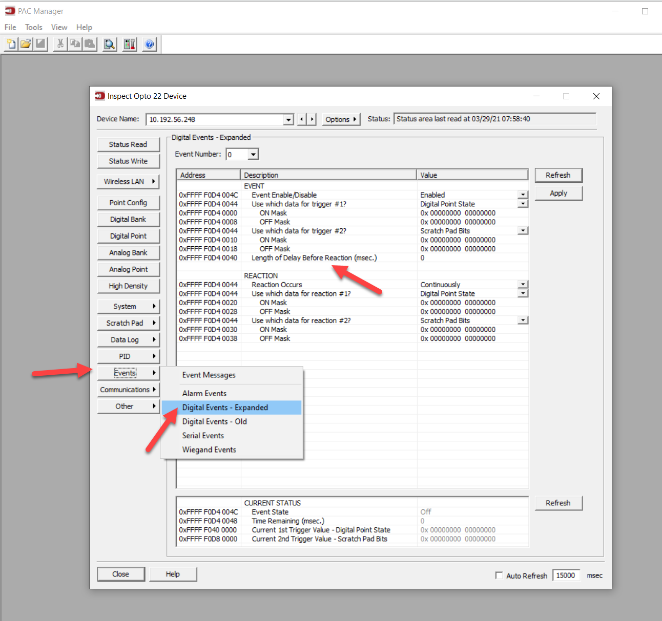
Setup a digital event: Turn on scratch pad bit #1 as soon as bit #0 goes high.
Setup a digital event: Turn off bit #1 after it goes high using a delay of X milliseconds. I make note of the memory address for the delay. Changing this address allows changing the ON time of the PWM.
Setup a digital event: Turn on bit #1 after it goes low using a delay of Y milliseconds. I make note of the memory address for the delay. Changing this address allows changing the OFF time of the PWM.
Setup an event message: Modify any desired memory map address when bit #1 goes high. This allows executing some actions on rising edges at precise intervals.
Setup a event message: Modify any desired memory map address when bit #1 goes low. This allows executing some actions on falling edges at precise intervals.
Few tips for things that threw me off temporarily:
Event message: To write a constant to a memory map use something like �_ (i.e. this writes 0). For floats make use of an ieee-754 calculator such as IEEE-754 Floating Point Converter to find the binary/hex representation. To write (i.e. transfer) data from another memory location, use something like $!B_F0D82000_. Note that even if one is transferring floats or integers, one has to pass them as binary masks (i.e do not use $!F_F0D82000_). If one uses the float mask, the address contents get formatted and passed as a string. The transferred string will then get interpreted as a 0 if lucky, or as some garbage number if unlucky.
One has to write this “code” without any labels, alias or comments, as the “Digital event” menu does not have such fields. The “Event Message” menu has a message_name but that’s about it. To the best of my knowledge, there is really no way of documenting the complex interaction of events right there where iit is needed. One has to either keep at hand all MEMMAP addresses or take note of the addresses in the relevant tabs of the inspect window. I am keeping a notepad with all addresses required for one event-reaction. @Beno: Is there a better way to document this?
This “code” gets saved into the OTG. If you import it to PAC Control (to get your I/O tags) and then (for some reason) decide to export it…tough luck. PAC Control does not retain the event information. So make sure to keep a copy of the OTG when you finish setting up the events in PAC Manager.
@Beno, @phillip Is there a way of editing the otg as a text file or the like, to easily copy reactions and replace memory addresses? I see I can open it as a text file, but I am unsure of the rules and syntax to edit it without corrupting it.
As an afterthought. One option could be to write comments in the OTG directly if such a feature exist and it is supported. Something like:
# IO rack configuration
IOUNIT...
# Digital modules configuration
DIN...
DIN...
# Analog modules configuration
AIN...
AIN...
# Event message configuration
EVENTMESSAGE...  # this event does something
EVENTMESSAGE... # this event does something else
# Scratch pad bits configutation
SCRATCHPADBITS... # this is the restart bit
Really solid write up. Thanks very much for coming back and not just saying ‘I got it going’, but putting the effort in to write it up.
There is a lot in there that I had forgotten about - sorry man - like the having to get the ieee of the hex. (I used the exact same website eleventy eight years ago).
After the burst water pipe incident, my co-worker (and I) agreed to write up the events in the chart that was tickling them. Another doc is just another thing to find / open and digest. The chart text area is not great, but its there in debug when you are looking at the code trying to figure it out.
There are some lose guidelines for messing with the OTG file, I can see if I can dig some up. I honestly have not hand edited one for a very long while. @philip I think you have?
I always always always take a PAC Manager snapshot of the brain/controller when you are done and after you make any changes. I would also do the OTG, but the PAC Man clone is what we used at the hospital a lot more.
I’ve only edited the OTG file for adding points not anything to do with events.
Due to the lack of self-documenting code and PAC Control not knowing about the modifications done through PAC Manager, I write any custom IO Unit configuration in my power up chart or IO enabler chart using Optoscript.
Here is a TPO PID setup (which can’t be configured in PAC Control’s PID configuration) as an example of my approach:
However you cannot write the event-reaction logic itself in optoscript or can you?
My understanding is that the event logic is setup in PAC Manager using the “Configure Digital Events” and “Event Messages” windows and then you can use PAC Control to adjust the parameters of the already configured event logic.
If there is a way to create events, as opposed to update event parameters, in PAC Control that would be less troublesome in terms of code maintenance.
Pretty sure can. You have all the addresses, just write the right stuff into each from PAC Control like Philips example (for TPO) and you are doing the exact same thing?
Yep, your addresses to write are right there on the left side in PAC Manager. Just write them in Optoscript using the WriteNumToIoUnitMemMap command. You will need to look in the protocol guide for the numeric values for the drop downs that are shown in PAC Manager (or you could just read that area out of your IO unit in PAC Manager using the generic read/write section).
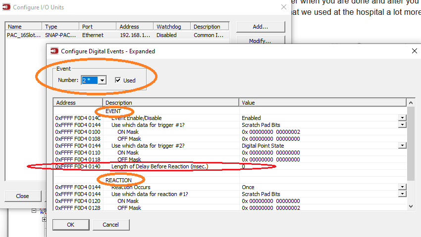
Sorry guys, I did not make myself clear. I understand you can edit the address as marked in red using WriteNumToIoUnitMemMap. However, the event must exist in the first place (marked in orange). I believe the events-reactions can only be setup in PAC Manager.
Ignore the above. Indeed, the events can be fully setup from scratch from optoscript too. One has to setup a rather long mask and write it to the appropriate event address. I was confused and thought that those event addresses were only allocated when the event was created in PAC Manager, but alas, they are always there, just full of zeros.
What I want to do is explained in pages 47 and 143 of the 1465_OptoMMP_Protocol_Guide.
Thanks again guys. I find this solution much obvious and easier to document than using the PAC Manager menus. Those are fine for simple logic, but one rapidly descends into chaos with more than a couple of chained events.
This. So much this.
The events are very powerful, but as I said up front, they are hard to wrap ones head around.
You need to use them as just one tool in your tool box, not the whole thing.
For ‘edge’ cases like yours, they are perfect so I am really glad you stuck with it and got them working the way you need.
Ok, I migrated all the Event-Reaction and Event-Message logic that I had in PAC Manager to OptoScript blocks in PAC Control. My reasons for this:
I can write extensive comments in OptoScript that I could not otherwise in PAC Manager. I find this very important when working directly with addresses.
I can move/group related events to my hearth’s content. This is not possible in PAC Manager.
If I need to replicate events, I can simply copy/paste some lines. Further, having all events as lines of code allows spotting errors easily. In PAC Manager each event is brought in its own tab and one cannot compare two or more events simultaneously.
The code is now in a single place, namely PAC Control. There is no risk of race conditions from logic being triggered by “hidden” or undocumented logic in the OTG, nor is there a risk of losing complicated event/reactions when exporting/importing the OTG. This also means that when doing version control, there is only a single place to look at.
One can express all addressing of one event in a relative fashion from a parent address. Similar to what @philip showed in his snippet (i.e. (2 * 0x80) + 0xF210004C;).
The translation of the events/reactions to Optoscript goes like this:
Setup a digital event: Turn on scratch pad bits #1, #2, #3, #4 as soon as bit #0 goes high.
// ** Sync trigger (event 0) - Start/reset with Scratch Pad Bit #0
// Setup Event for bootstrapping all other events as soon as the signal goes high
STATUS = WriteNumToIoUnitMemMap(PAC_16SlotRack_200L, 0xF0D40044, 1081600); // 32-bit
// Configure trigger ON mask
STATUS = WriteNumToIoUnitMemMap(PAC_16SlotRack_200L, 0xF0D40000, 1i64); // 64-bit
// Configure reaction ON mask
STATUS = WriteNumToIoUnitMemMap(PAC_16SlotRack_200L, 0xF0D40020, 30i64); // 64-bit
Setup a digital event: Turn off bit #1 after it goes high using a delay of Y milliseconds. I make note of the memory address for the delay. Changing this address allows changing the ON time of the PWM.
// ** First Channel (event 1 and 2) - Signal tracked with Scratch Pad Bit #1
// Setup Event for lowering the signal after Y milliseconds of being set high
STATUS = WriteNumToIoUnitMemMap(PAC_16SlotRack_200L, 0xF0D400C4, 1081600); // 32-bit
// Configure trigger ON mask
STATUS = WriteNumToIoUnitMemMap(PAC_16SlotRack_200L, 0xF0D40080, 2i64); // 64-bit
// (Optional) Make sure the trigger OFF mask is disabled
STATUS = WriteNumToIoUnitMemMap(PAC_16SlotRack_200L, 0xF0D40088, 0i64); // 64-bit
// Configure reaction OFF mask
STATUS = WriteNumToIoUnitMemMap(PAC_16SlotRack_200L, 0xF0D400A8, 2i64); // 64-bit
// (Optional) Make sure the reaction ON mask is disabled
STATUS = WriteNumToIoUnitMemMap(PAC_16SlotRack_200L, 0xF0D400A0, 0i64); // 64-bit
Setup an event message: Modify any desired memory map address when bit #1 goes high. This allows executing some actions on rising edges at precise intervals.
// Setup message to write local MEMMAP when bit 1 goes high - First Channel ON
STATUS = WriteNumToIoUnitMemMap(PAC_16SlotRack_200L, 0xF1200004, 2i64); // Scratch Pad Trigger ON mask, 64-bit
// (Optional) Disable off mask
STATUS = WriteNumToIoUnitMemMap(PAC_16SlotRack_200L, 0xF120000C, 0i64); // Scratch Pad Trigger OFF mask, 64-bit
// Set the parameter to write. Here we write a setpoint stored in the float scratch pad
STATUS = WriteStrToIoUnitMemMap(PAC_16SlotRack_200L, 0xF1200040, “$!B_F0D82000_”); // Message text, String
// Set the address to write. Here we write the desired address in the module module
STATUS = WriteNumToIoUnitMemMap(PAC_16SlotRack_200L, 0xF1208000, 0xYourAddress); // Destination address, 32-bit
// Set the I/O unit of the address to write. Here we write an IP of 0.0.0.0 to write to the local I/O unit
STATUS = WriteNumToIoUnitMemMap(PAC_16SlotRack_200L, 0xF1208004, IpAddressStringToInt32(“0.0.0.0”)); // IP address of destination I/O unit, 32-bit
// Set the UDP port. Here omitted since it is ignored when setting the IP to 0.0.0.0
// Set how frequent to write the message. Here we write 0 for a single write.
STATUS = WriteNumToIoUnitMemMap(PAC_16SlotRack_200L, 0xF120800C, 0); // How often to copy data, 32-bit
Notes on the bolded numbers:
The 1081600 comes from:
Trigger #1 = Scratch Pad Bits = 15 -> 32768
Trigger #2 = [not used] = [none] -> 0
Reaction #1 = Scratch Pad Bits = 20 -> 1048576
Reaction #2 = [not used] = [none] -> 0
Reaction occurs once = bit 8 -> 256
Event configuration word: 32768 + 0 + 1048576 + 0 + 256 = 1081600 or 0x0010 8100 or 0001 0000 1000 0001 0000 0000
The suffix i64 needs to be there where the function expects a 64bit parameter. Otherwise any constant that can be fit in a 32bit integer will be cast as a 32bit integer, resulting in garbage being stored in the 64bit address. The i64 suffix casts the number as 64bit.
Plugins are passed as strings, thus one has to use “WriteStrToIoUnitMemMap”. Recall that for the value pointed by the plugin to be casted as a number and not as a formatted string, the notation must be of the form “$!B_F0D82000_”
One final note.
I ran the software PWM as documented above in two channels doing:
Case A:
ON for 1000ms, Off for 1000ms
ON for 1000ms, Off for 1000ms
They would run perfectly in sync for hours
But when doing
Case B:
ON for 2000ms, Off for 2000ms
ON for 1000ms, Off for 1000ms
They would go out of sync after few minutes. I would have expect them to flash ON in sync every 2 seconds.
I believe the reason for this is machine rounding. The delay value of “1000” gets stored in machine notation say (for simplicity) as 999.9.
In case A both channels lag by 0.1ms. Thus, they both run in sync, albeit at a slightly incorrect frequency.
In case B, even if the rounding error is the same for 2000 and 1000 (which it is not likely), the difference in frequency will cause one channel to lag more frequently than the other, resulting in a visible asynchronicity after a while.
I guess anyone thinking on doing software PWM should keep that limitation in mind. I guess one could round the numbers based on the opto-brains epsilon, but that is an idea for another post.
Far out. What an awesome reply!!
Solid gold. I am going to bookmark this thread as THE standard for event reactions and PWM!!!
Thanks so much for coming back and giving so much knowledge to the group.