My use case was being able to monitor a small number of objects from an Epic with my building automation system using BACnet protocol. I was able to accomplish this using Node Red.
To get the set up right I had to research information from several different sources. I put together a spreadsheet to have all of the information in one place. Using the information in this spreadsheet you can read or write to/from your Epic to BACnet. I will share the spreadsheet at the link below in case anyone else has a similar project. Please let me know if you have any questions.
Wow! Mikel, first up, welcome to the forums and secondly, awesome content!
Thanks so much for sharing the spreadsheet. There is a wealth of great information there.
I wish I had more ‘like hearts’ to give!
Thanks so much for sharing! We have two Carrier process chillers that talk Modbus and BacNet. I am currently reading the data via Modbus but will give BacNet a try.
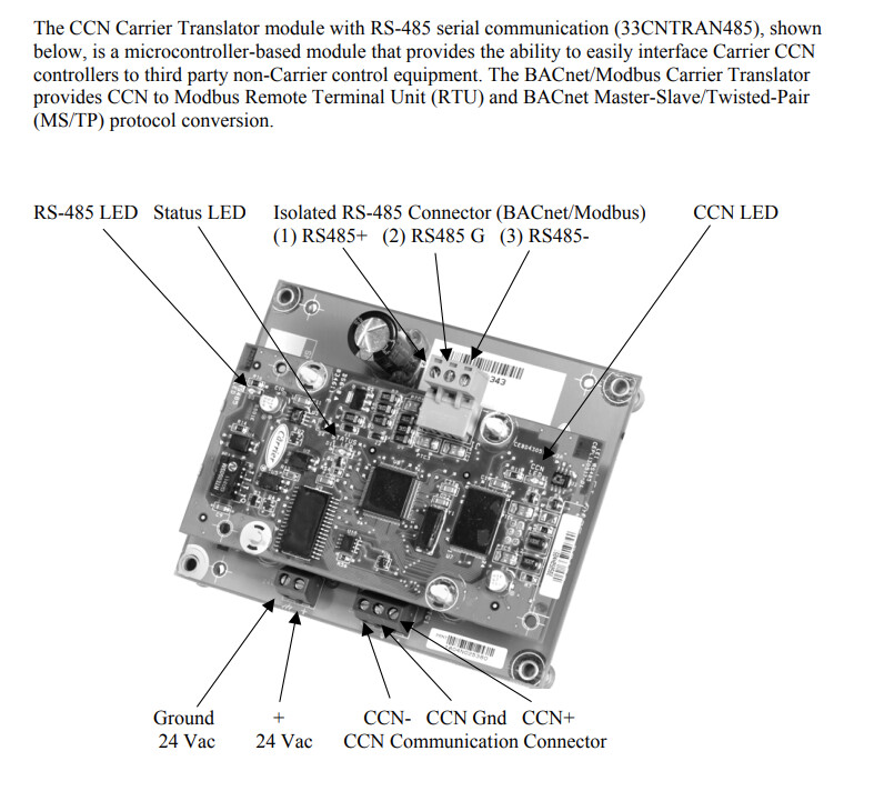
Yes, it was actually quite easy. Just have your Opto22 device (or whatever you may have running Node-RED) query the data on the chiller (with the CCN translater) using standard Modbus (RTU) nodes and do what you want with that (send to database, use in Opto program, etc.). The trickiest part was the initial configuration and making sure the Carrier technician assigned the addresses. Here is what I have from my notes (we have two chillers and are querying both via Node-RED, hence the two differen Modbus addresses).
Chiller A
Chiller B
Modbus Address
32
6
Data Bits
8
8
Stop Bits
1
1
Parity
none
none
Baud Rate
19200
19200
Flow Controll
Off
Off
and here are the parameters we can see (there may be more, but this was a while ago and I cannot recall exactly).
Point Name
Writeable
Description
Value
Units
Modbus Register (hex)
Modbus Register (decimal)
CTRL_PNT
W
Control Point
-20 to 70
°F
0x400A
16394
EWT
Entering Fluid Temperature
snnn.n
°F
0x400B
16395
LWT
Leaving Fluid Temperature
snnn.n
°F
0x400C
16396
EMSTOP
W
Emergency Stop
Enable/Emstop
Enable
0X400D
16397
MIN_LEFT
Minutes Left for Start
00:00 to 15:00
minutes
0x400E
16398
COOLPMP1
Cooler Pump Relay 1
On/Off
0x400F
16399
COOLPMP2
Cooler Pump Relay 2
On/Off
0x4010
16400
PMP1_FBK
Cooler Pump 1 Interlock
Open/Close
0x4011
16401
PMP2_FBK
Cooler Pump 2 Interlock
Open/Close
0x4012
16402
COOLFLOW
Cooler Flow Switch
Open/Close
0x4013
16403
STAT
Control Mode
0=Test 1=Local Off 2=CCN Off 3=Clock Off 4=Emergency Stop 5=Local On 6=CCN On 7=Clock On 8=Heat Enabled 9=Pump Delay
0x4000
16384
OCC
Occupied
No/Yes
0x4001
16385
CHIL_S_S
W
CCN Chiller
Start/Stop
0x4002
16386
LSACTIVE
Low Sound Active
No/Yes
0x4003
16387
ALARM
Alarm State
Normal/Alert/Alarm
0x4004
16388
DEM_LIM
W
Active Demand Limit
0 to 100
%
0x4005
16389
MODE
Override Modes in Effect
Yes/No
0x4006
16390
CAP_T
Percent Total Capacity
0 to 100
%
0x4007
16391
STAGE
Requested Stage
0 to 99
0x4008
16392
SP
Active Setpoint
-20 to 70
°F
0x4009
16393
LEADPUMP
Lead Pump
0x4014
16404
ROT_PUMP
W
Rotate Cooler Pumps Now
No/Yes
0x4015
16405
HC_SEL
Heat/Cool Select
Heat/Cool
0x4016
16406
CALCTONS
W
0x4017
16407
CAPA_T
Percent Total Capacity, Circuit A
0-100
%
0x4018
16408
CAPA_A
Percent Available Capacity, Circuit A
0-100
%
0x4019
16409
DP_A
Discharge Pressure, Circuit A
nnn.n
PSIG
0x401A
16410
SP_A
Suction Pressure, Circuit A
nnn.n
PSIG
0x401B
16411
HSP
W
Head Setpoint
nnn.n
°F
0x401C
16412
TMP_SCTA
Saturated Condensing Temperature, Circuit A
snnn.n
°F
0x401D
16413
TMP_SSTA
Saturated Suction Temperature, Circuit A
snnn.n
°F
0x401E
16414
SSTA_AVG
0x401F
16415
TMPISSTA
0x4020
16416
EXV_A
EXV % Open (EXV = electronic expansion valve), Circuit A
nnn
%
0x4021
16417
VHPA_ACT
Variable Head Pressure Output, Circuit A
nnn.n
milliamps
0x4022
16418
TMP_RGTA
Compressor Return Gas Temperature, Circuit A
nnn.n
°F
0x4023
16419
DISGAS
Dischage Gas Temperature
nnn.n
°F
0x4024
16420
SH_A
Suction Superheat Temperature, Circuit A
nnn.n
Δ°F
0x4025
16421
SPR1_TMP
Spare 1 Temperature
nnn.n
°F
0x4026
16422
K_A1_RLY
Compressor A1 Relay
On/Off
0x4027
16423
A1UNLTME
W
Compressor A1 Unload Time
nn
seconds
0x4028
16424
K_A2_RLY
Compressor A2 Relay
On/Off
0x4029
16425
K_A3_RLY
Compressor A3 Relay
On/Off
0x402A
16426
MLV_RLY
Minimum Load Valve Relay
On/Off
0x402B
16427
CCHA
0x402C
16428
K_A1_FBK
Compressor A1 Feedback
On/Off
0x402D
16429
K_A2_FBK
Compressor A2 Feedback
On/Off
0x402E
16430
K_A3_FBK
Compressor A3 Feedback
On/Off
0x402F
16431
CAPB_T
Percent Total Capacity, Circuit B
0-100
%
0x4030
16432
CAPB_A
Percent Available Capacity, Circuit B
0-100
0x4031
16433
DP_B
Discharge Pressure, Circuit B
nnn.n
PSIG
0x4032
16434
SP_B
Suction Pressure, Circuit B
nnn.n
PSIG
0x4033
16435
TMP_SCTB
Saturated Condensing Temperature, Circuit B
snnn.n
°F
0x4034
16436
TMP_SSTB
Saturated Suction Temperature, Circuit B
snnn.n
°F
0x4035
16437
EXV_B
EXV % Open (EXV = electronic expansion valve), Circuit B
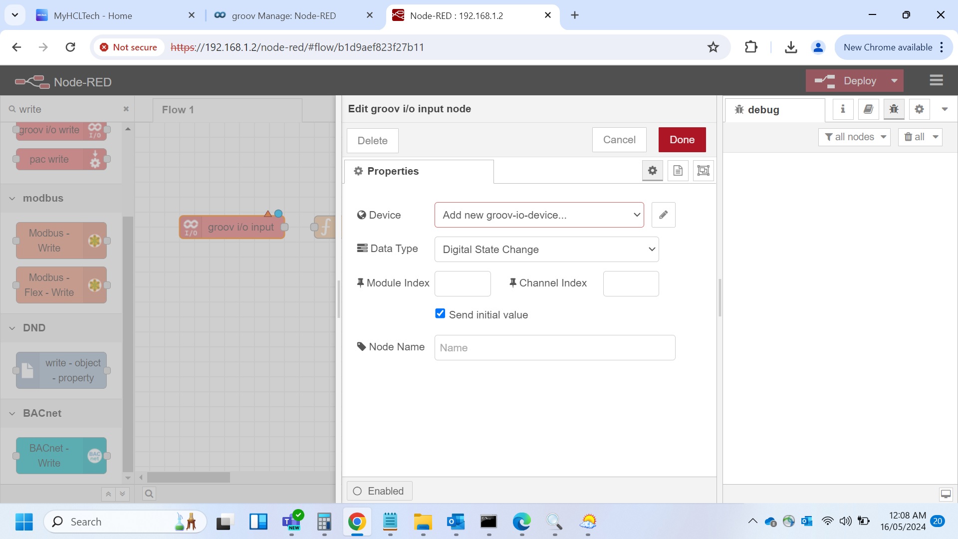
You must click the pencil icon beside the red box and enter your details.
In this case, it’s the API key you copy from an admin account in groov Manage.
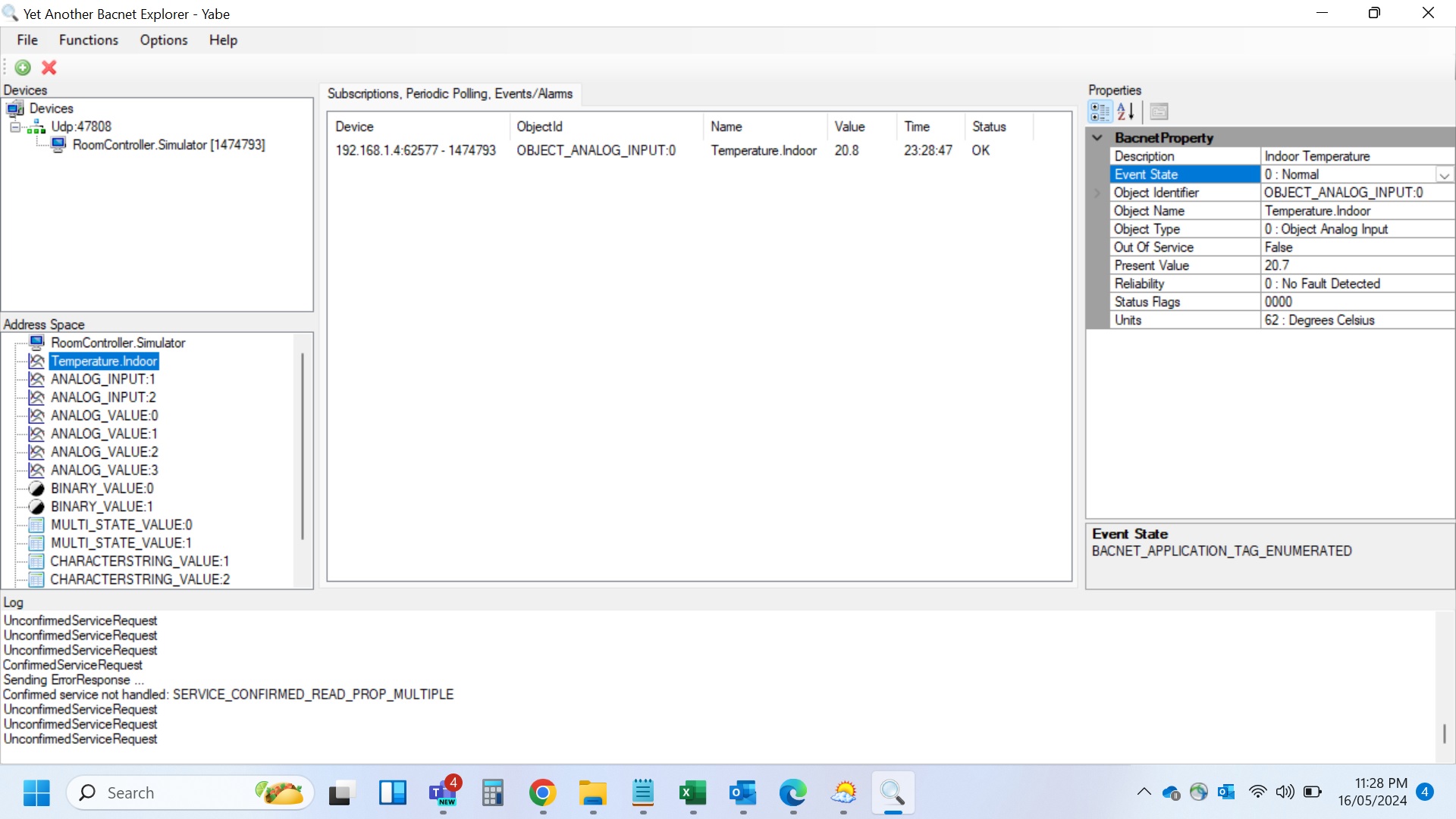
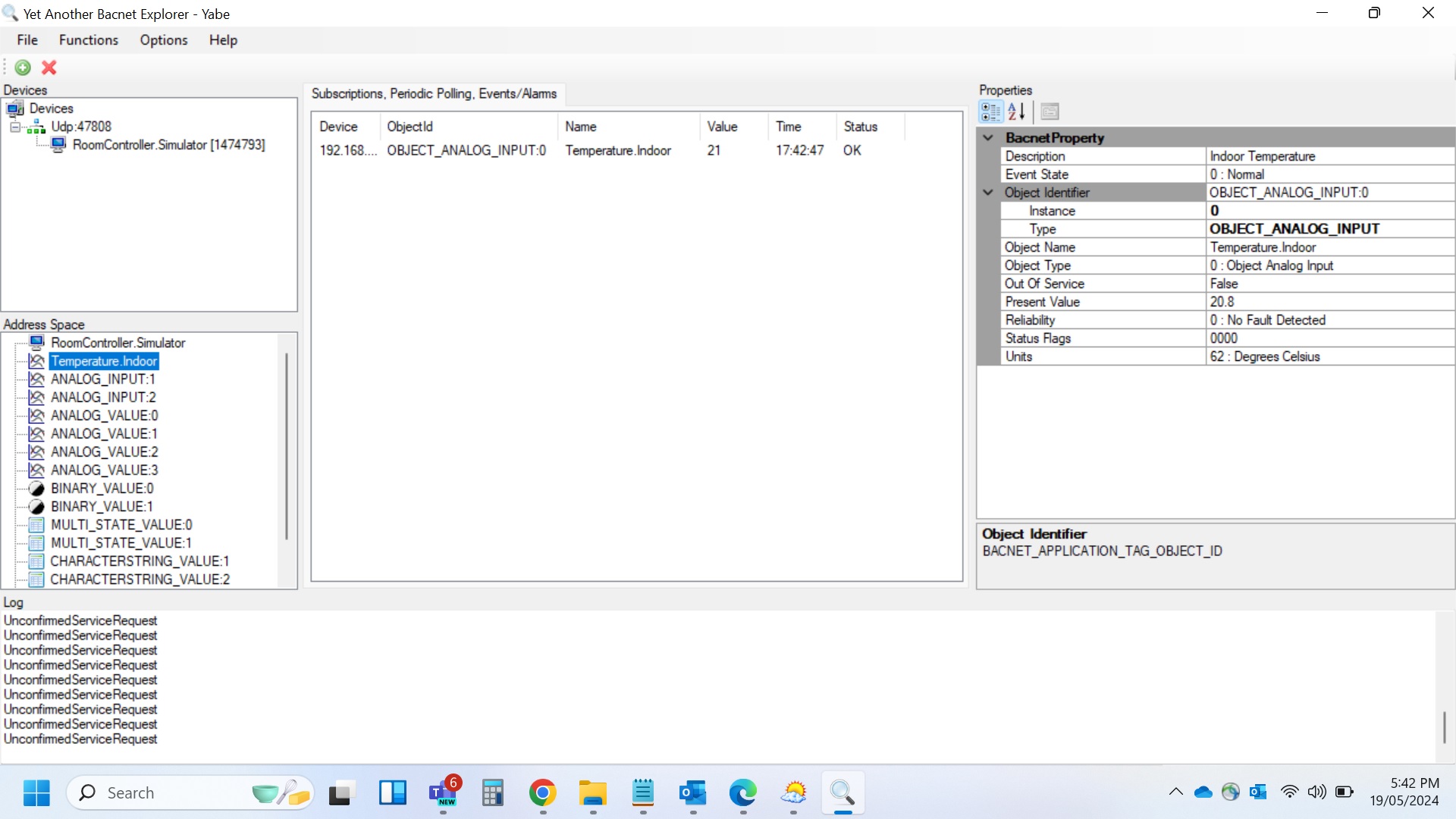
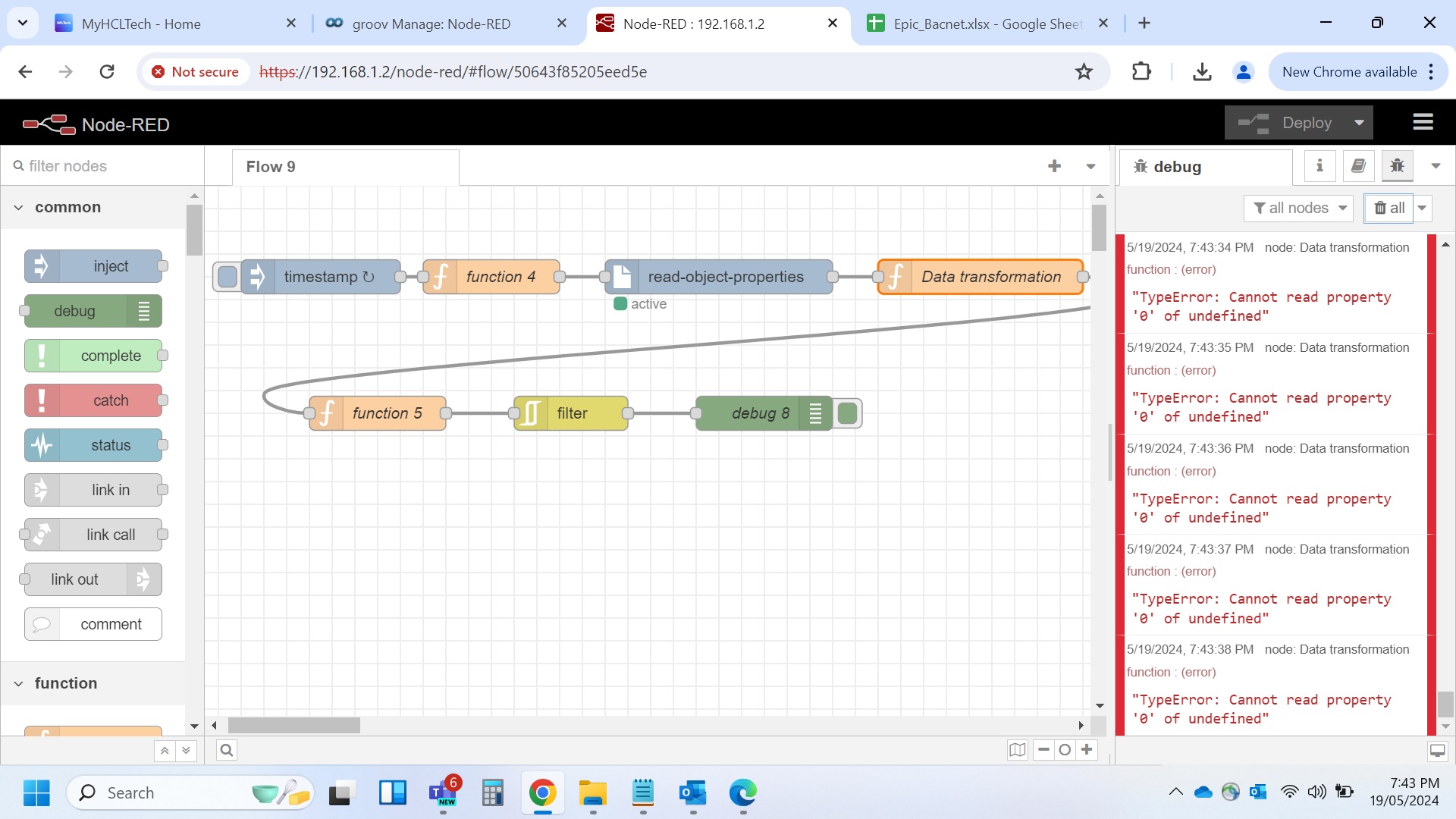
I am trying to read room temperature simulator over BACnet IP from Node red. By following the steps as advised in Mike’s(Ist ) note, there is an error encountered in Data transformation block as “TypeError: Cannot read property ‘0’ of undefined”. Please help to - 1) fix the above error. 2) Also please validate the function in the Ist function block with respect to the attached settings of the BACnet IP device(room temperature simulator.
Code in the Ist function block:-
msg.deviceId = 0;
msg.address = “192.168.1.4”;
msg.inputType = 0;
msg.bacnetID = 0;
Then please suggest the below values in light of the above screenshot from Yabe for the BACnet simulator:-
msg.deviceId = 0;
msg.address = “192.168.1.4”;
msg.inputType = 0;
msg.bacnetID = 0;
Thanks Mikel for your response. With the above code snippet, the below error is still encountered. Pls help to fix this error message-
“TypeError: Cannot read property ‘0’ of undefined” at Data transformation block
There is no ‘error below’ posted.
That error you mention is a Node-RED error simply saying that you don’t have any variable named, so hence it’s ‘undefined’. It’s a common Javascript error.
You will need to learn a few Javascript basics and you will need to learn some Node-RED basics on how to correctly debug your code.
There are many YouTube videos on each of those topics.
Thanks Beno for your prompt response. I want to read indoor temperature of BACnet temperature simulator using Node Red. It may be due to the undefined variable or so that the PV of indoor temperature doesn’t appear at the debug window. Request your help here. How if we connect virtually(MS teams meeting) to read this parameter
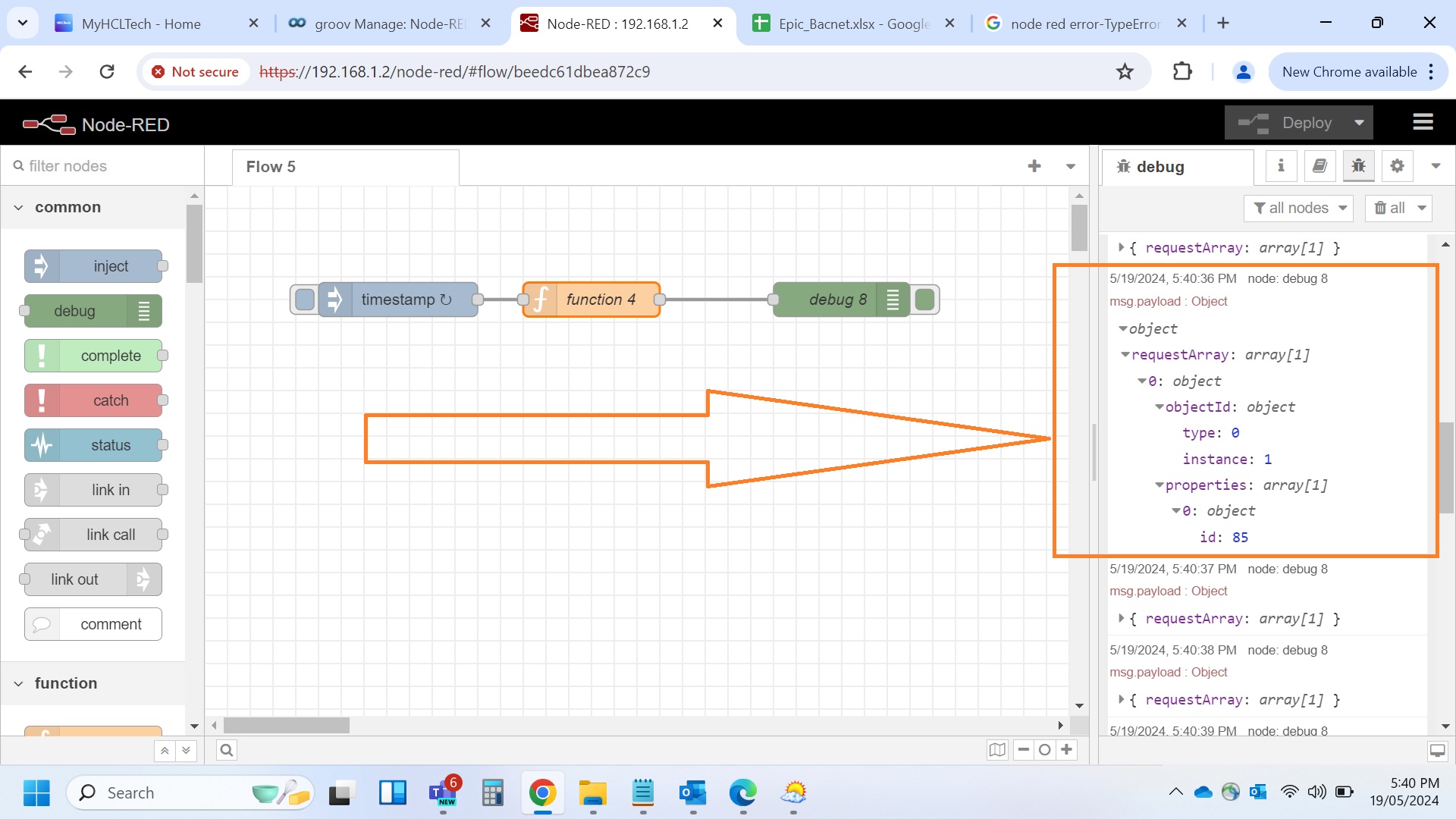
I’d like to read temperature value from bacnet simulator. When the below code is executed then the real time value as shown in snapshot from Yabe doesn’t appear. So what more should be added to the code so that the PVs gets seen in Node red-
msg.payload = {};
msg.payload.requestArray=[
{ objectId: { type: 0, instance: 1 }, properties: [ { id: 85 }] },
]
return msg;
You don’t have the read object properties node in your flow. You need to install node-bacnet-contrib-extended if you haven’t already. Please see the spreadsheet I have shared above and follow the steps to read a single object
Thanks Mikel for your response. After implementing per your valuable suggestion, the error message as shown in 3.jpg appears. Node-bacnet-contrib-extended is already installed. There is no change in function blocks/code as suggested by you earlier. Please help to read PV of Indoor temperature by fixing the error message attached herewith