I want to wire an analog signal from a loop powered device to my groov RIO.
Currently, there is a digital output on ch2 and ch9.
I would like to wire this analog input to ch0.
I have 1 24VDC PSU in the panel, and I’m not sure how to wire this.
I follow the diagram provided by the manufacturer and the groov RIO data sheet, but I’m getting invalid value on the analog signal.
If I disconnect the other devices and just leave the analog input connected, I’m reading the correct values.
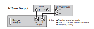
This is the wiring diagram provided for the an analog signal:
Keep in mind that the RIO has a common ground/neutral for all inputs (analog and digital).
Sounds like your analog input 24v PSU has a different ground than the digital inputs so when you hook it up, you are getting the invalid readings because the 4-20 transmitter is getting extra current on the ground from the digital inputs.
ie, its not a wiring issue, its a grounding issue.
Looking at your diagram you need to setup your 4-20ma loop so the negative of the power supply is interfacing to the RIO. If its the same 24vdc supply then it should work.
See the RIO wiring examples in the manual.
Beno is correct, the issues is between your CH2 point and the CH0 point, since CH9 is isolated. Check the common connection on the wiring diagram and try not to “ground” your negative rail of your power supply if you can.
If you have a diagram of the wiring for your CH2 point we could give more advice.
I got it working this morning, just some weird behavior noticed.
The analog input is a current transducer for a motor, being controlled with a HOA and the digital out on the RIO.
In hand mode, the transducer reads around 1.7 amps more than in auto mode.