We are using Snap pack R2 Controller with 32 channel Analog Inputs. I want to use Snap pack R2 controller as Modbus TCP/IP slave. I configured all Analog Inputs and also gone through [B]“PACModbusSalve”[/B] subroutine but couldn’t get the data.
My Configuration
ch1 - input type 4 to 20 mA. High Limit - 80, Low Limit - 20
As per above given configuration kindly provide the Modbus mapping or kindly guide me to how to use PACModubusSalve subroutine for above given configuration.
[LEFT]If you only want to read analog inputs you can use the built in Modbus. Are you aware it is bult in?[/LEFT]
[LEFT]If you need other data from the strategy then the Modbus integation kit can be used. The slave subroutine is included.[/LEFT]
[LEFT] [/LEFT]
[LEFT]To use the kit there is a setup to set data type and communication handle.[/LEFT]
[LEFT]The data type for a float is 2 or 3.[/LEFT]
[LEFT]The analog inputs values will need to be moved into the holding register 4x float table.[/LEFT]
You don’t actually have to move any values, they’re already in the registers automatically, you just need to calculate the Modbus address that corresponds to the memory map address (as shown in the links mentioned above).
Here’s an analog input example:
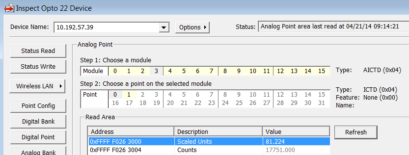
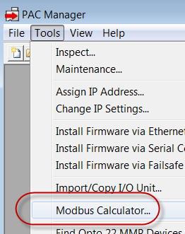
First I need to find the memory map address of the point I’m interested in. I can do this using form 1465 (link in my previous post) or by using PAC Manager.
For this particular example, I’m using the temperature from my ICTD module in position 3 (point 0), which is memory map address F0263000:
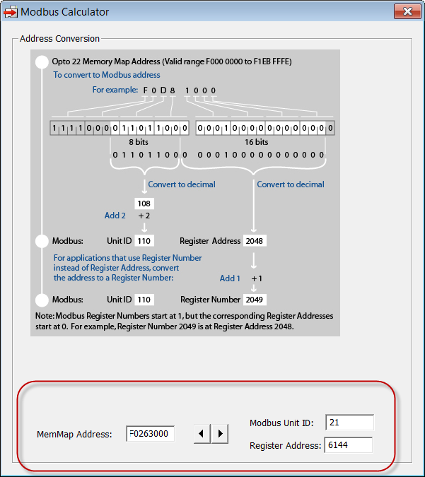
Now I can use the PAC Manager’s Modbus Calculator to find the corresponding Modbus address, to see that address F0263000 corresponds to Modbus Unit ID 21, register address 6144: