Hello
I have a circuit consisting of an emergency stop button, a SNAP-IDC5, a reset button and a relay coil with a resistance of 600ohm.
The circuit is powered by 24v DC supply.
The SNAP-IDC5 acts simply as an indication that the Emergency Stop button circuit is healthy.
The 24V supply goes through the E Stop button and then through the OPTO module and on to the reset button and then onto a relay coil which energises contacts off the relay.
When the reset button is pressed to energise the relay coil there is only about 4 volts on the ‘out’ side of the OPTO module, the OPTO module therefore seems to be ‘dragging’ down the voltage to a level where it isnt sufficient enough to allow the relay coil to be energised.
Has anybody any ideas why the OPTO card is acting as a large resistance and ‘dragging’ down the voltage?
Kindest regards
Paul
The SNAP-IDC5 should be in parallel with the part of the circuit that you want to know is receiving voltage, like the relay coil. When the relay coil is receiving voltage, the SNAP-IDC5 will be ON and when the relay coil is not receiving voltage, the SNAP-IDC5 will be OFF. The SNAP-IDC5 has 15,000 ohms of resistance. See the Specifications tab at this link: Opto22 - SNAP-IDC5 - SNAP 4-Ch 10-32 VAC/VDC Digital (Discrete) Input Module
Thank for your reply Mary
So the internals of the OPTO module have a 15000ohm resistance?
I should check what current is required fort he relay coil to operate correctly.
Kindest regards
Paul
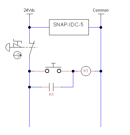
To illustrate Mary’s suggestion, below is an example circuit with a normally closed E-stop, a normally open momentary reset button, a relay, and the IDC module placed to detect that the circuit has power.
Hi and thanks for your schematic.
I may be being a lttle dim but wouldn’t the OPTO module always detect a power to the circuit as it always connected across the 24V and common terminals?
Sorry if I have misunderstood the drawing, I am not expert in electrical circuits.
Kindest regards
Paul
I may have misinterpreted your goal of monitoring the “health” of the circuit. You are correct, the example I provided uses the IDC5 module to check for presence of the 24V supply.
If you want to know the status of the E-stop button, the signal into IDC5 module could be moved to after the E-stop button
If you want to know if voltage is being provided to the relay, the signal could be moved to after the momentary button.
The point that I was illustrating is that the module should be in parallel with the K1 load, not in series with it.
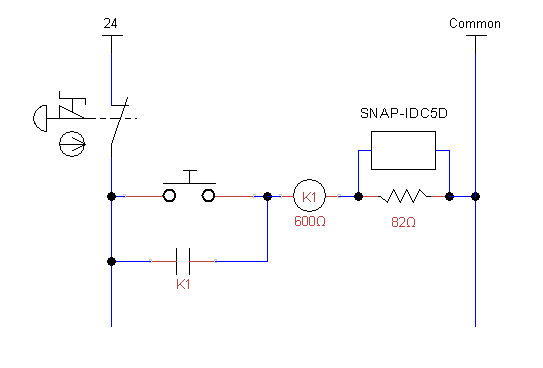
If you absolutely need to know that current is actually flowing through the relay, a current sensing module could be used, or a resistor could be added that would not drag down the relay voltage to unusable levels. The SNAP-IDC5 requires 10V to trigger, which would only leave 14V for your relay and is probably below the pickup voltage. However, a SNAP-IDC5D module only requires 2.5V to trigger, which you could safely steal and leave 21.5V for the relay. Something like the below:
Along the same line of thought, if you want to stay with the SNAP-IDC5 module, you could switch to a 12V relay, and size the resistor to be equal to the resistance of the relay.
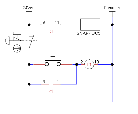
I should probably have pointed out that the most typical way to use a digital module to see what the circuit is doing is by using a set of contacts on the relay. For example, if you have an 11 pin ice cube relay, you could do something like the schematic below.
If a person’s safety depends on this E-stop circuit functioning properly, please do not rely on semi-anonymous suggestions made in an online forum. There are detailed requirements for how to go about designing this, NFPA 79 is a good starting point in the US, or you may want to talk to a licensed engineer. Relays must be rated for use in safety circuits, and are constructed differently than a common ice cube relay. Safety relays frequently have an auxiliary contact that could be used to indicate status to a digital input module, and would take the place of the NO contact between pins 9 and 11 that is shown below.