What is the best practice for viewing an input on a RIO in groovView?
What is the best practice for viewing an input on a RIO in groovView?
Configure the RIO as an Opto 22 I/O unit.
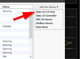
Once you do that all the I/O (inputs and outputs) will show up in the groov View tag tree under that device.
Thanks Beno, I did that yesterday and thought I had to configure a tag for the RIO in groovView. I created a tag with the same name as the input I created in groovManage for the RIO. So, I deleted the RIO in groovView and re added it. Now the tag shows up in the module section for the device, it’s working now. Larry
Yeah, sorry on my behalf, that was a pretty big assumption from me…
The correct sequence is to configure the channel / point names in groov Manage on the RIO.
Once you are happy with them, then add the device in groov View.
If you don’t have any channel names then groov View will come up blank.
Still learning about groovRIO, I am trying to create a power sensor alarm event. I have an AC adapter plugged into the same outlet that I have a UPS powering the RIO power supply. The AC adapter has a 12VDC output, which I connected to the RIO as a voltage input. Logically I would set up an event in groovbuild for when the state of the voltage input is false to send the alarm. With a PAC I would create a integer in the strategy to represent the state of the input, but not with the RIO. What I have tried isn’t working. Any suggestions?
Odd.
I had a moment just now so setup the same sort of test.
I have a 12 v power adapter that I stripped the wires and put into channel 1 on my RIO.
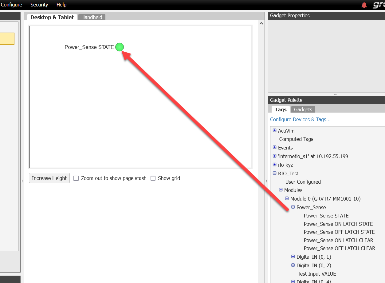
I could see the LED go on and off on the RIO, in groov Mange, you can see the state change.
Then on my groov View I attached it to an LED gadget to see that go red/green.
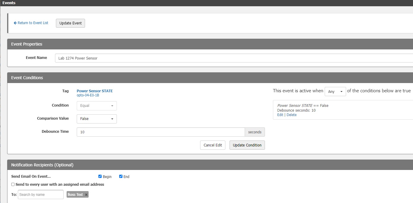
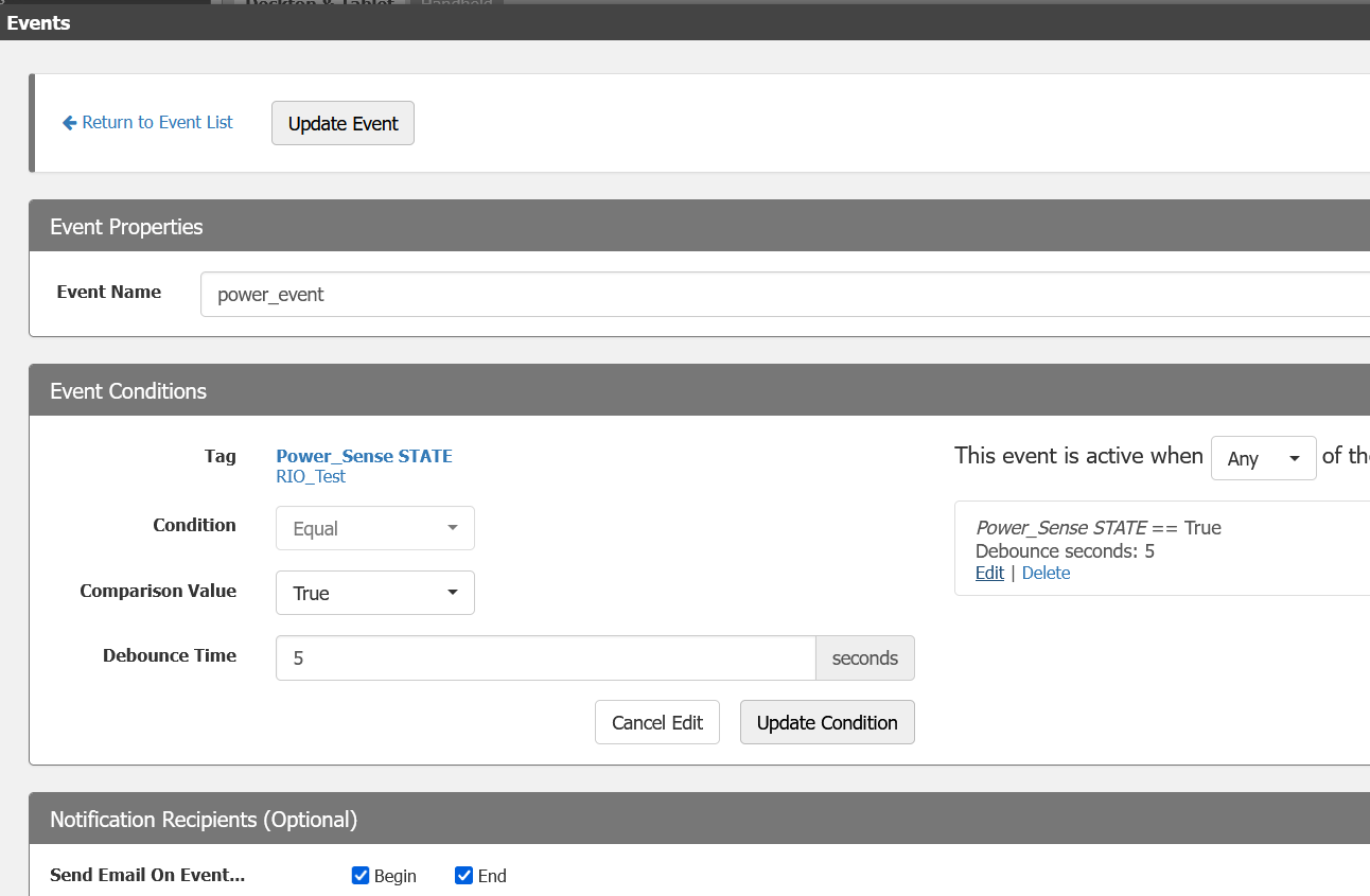
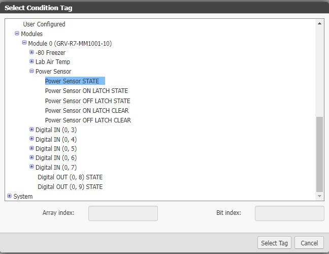
From there, I configured an event.
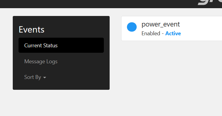
Then when I change the state of the power, I see the event come and go from the debounce time.
Do you have the digital point attached to a gadget?
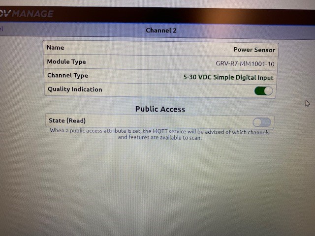
Yes, upon further troubleshooting, I discovered that when I disconnect the AC adapter from the outlet the RIO Channel 2 is still illuminated, the groovView gadget still states it has power, in the ON state. Any thoughts on that mystery?
I configured the channel to be a 5-30VDC Simple Digital Input. The AC adapter output is 12VDC.
Could it be that the adapter you are using takes a while for the caps to bleed down the voltage?
I am completing removing the AC adapter from the outlet. I would expect the indicator on the RIO for Channel 2 would turn off instantaneously. Oh, not sure if AC adapters have caps in them. I will go try to remove the wire from the RIO channel 2 input and see what happens. Thanks!
It won’t work like that - the RIO doesn’t put much of any load when measuring voltage so the adapters output capacitors will hold it above 5VDC for a while - check the DC voltage with a meter when you unplug it.
You could also disconnect the wires from the RIO to see if the state goes to off.
You’re correct! I disconnected the AC adapter wires from the RIO and the input state turned OFF. Well, learn something new everyday! So, any advice on how to make it act more like a switch? Put a high value resister across the RIO terminals? I have used AC adapters connected to ODC5SRC on a PAC rack and it works fine, I guess the ODC5SRC has a higher internal resistance?
Yes, a 3k or so resistor across the terminals should work fine.
That would be lower internal resistance (input impedance) in that case.
Thanks Philip! I will try that out and test it tomorrow, I am on the US East coast, ready to call it a day!
Okay, first a correction, I use the IDC5D on a PAC rack for power sensor, not the ODC5SRC. No resistor needed. Maybe bc AC adapters vary in their capacitance?
For the RIO I put a 3K resistor across the input, didn’t seem to drain the caps in the AC adapter, so I put a 10K and it drained the caps in about 30 seconds.
Thanks again!
Just FYI. The SNAP IDC5 have a current limit resistor hooked to the red LED, so the LED is actually running from the input voltage. That is what is draining down the caps in the adapter and at 10ma or so driving the LED, it will happen in a few seconds for most adapters.
The RIO drives its channel LEDs from a totally different circuit, so the LED is not actually connected to the input device. Hence it places hardly any load at all on the adapter, hence it stays on for ages.
I am currently working on a series of videos about the RIO I/O and will make a note to comment on this aspect when I get to the digital input type as I am sure it will come up again.
Thanks for keeping us all in the loop, this sort of feedback is super helpful to everyone.
The lower the resistance, the faster it should drain.