This is mainly a question about OptoControl, but as we move our hardware to groov, we are looking at ways to streamline our process.
We’ve recently had a lot of issues (I/O units becoming disabled and taking to long to be able to get them communicating again is the primary issue) communicating over serial cables on our LCM4 controllers so we’ve changed how we read/write to the I/O using the the following commands:
Currently, we have 2 B3000, 2 PACR1, 11 G4D16R, 13 G4D32RS, and 10 G4A8R in our setup. We have a chart that issues the above listed commands to write to and then read all of the values to/from the modules. That chart takes an average of 2 seconds to complete.
Our issue is that 2 seconds can cause issues with many of our error checking systems. Does anyone have any suggestions in how we can speed up this process?
I have just started the somewhat mammoth task of reviewing and rewriting the optimization and best practices documents that cover your post just now so this sort of concept question is on my mind.
From a high level, you want this doc: https://documents.opto22.com/1776_Optimizing_PAC_Project_System_Performance.pdf
Pages 1 to 10 will have the most bang for your buck. BUT. I have to ask, do you have PAC Display in the mix here?
If so, do you connect your graphic elements to the I/O unit or those tables?
The correct (and only) answer is ‘to the tables’. If you connect them to the I/O points, then the PAC Display scanner and your your ‘serial IO’ chart will be fighting each other for the serial bus.
Think of Ethernet as an autobahn. Lots of packets all moving different ways at high speed.
Think of serial as a one lane dirt road. It does not matter if you send a motorbike or a bus down that dirt road, the police block the road off till it comes back safely.
PAC Display getting one tag is a motorbike. Your ‘serial IO’ chart is sending a bus to get the entire rack of IO.
Take a guess which is more efficient…
Ok, so now that you have spent a few hours or a few days (depending on how many PAC Display pages you have and now many elements are on each page) making 110% sure you don’t have a single I/O tag anywhere in your entire PAC Display project, that they are ALL connected to the tables in the Ethernet controller that is running the ‘serial IO’ chart, what sort of speed bump do have now?
After that, we need to dig into how you are sending that table bus down the one way dirt road…
Outside of the chart doing all of the communication we use variables as a replacement to the I/O point. Inside the chart, we move all of those variables to or from the table as necessary. We are using OptoDisplay and I have already changed everything there to the variables also so the I/O point is not used anywhere.
Here is an example of our code that reads from a B3000.
Regarding the chart doing the communications…
I am not sure why you are testing the ‘isIoUnitCommEnabled’ when getting the table, whats your thinking there?
I would have thought you would have an I/O checker / enabler chart that is part of the ‘get table’ aspect of the serial IO chart. That way you know you can just grab each table, if its not online, you don’t even try, just skip over that one till its back online (why your first post comments about your I/O going offline is a bit of a question for me, I have not had that issue with serial I/O in the past, its been pretty robust for me, so perhaps there is some wiring or termination issues that should be investigated vs ‘its always done that, lets just code around it’).
The key is to only have one chart accessing each serial port. Its the gatekeeper.
By only having one chart per serial port (not sure if you can or have, but splitting your serial I/O units across as many ports as you can is important. You may have just wired them or let them expand over time as one long serial drop, but if you can segment the serial units across a few of the controller serial ports that will help speed things up a LOT) you ensure that the one lane dirt road is used to its maximum time slice efficiency.
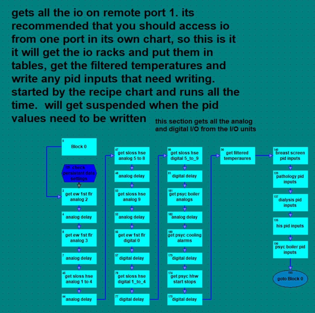
Here is a screenshot of part of an old serial IO chart from years back that helps explain one more important aspect…
The key here is the different delays for the different types of IO racks.
Analog, digital and mixed. You will have three different variables that will need to be tuned for your serial loops. I cant suggest values as things like baud rates and length will come into play and so on. You will need to experiment to find the best values for each of your serial loops and racks. Perhaps you might even up with a delay for each IO rack.
I made them persistent so I could tune them live and they would be locked in each download/reboot there after.
The way we used to do it in Opto control for the older serial I/O was to use event reactions on the I/O to create interrupts if something changed. Any changes would create an interrupt and cause the controller to read the I/O unit. It was a lot to setup but it worked great and only read the I/O points when necessary which opened up a lot of bandwidth.