PID Scan rate: why use 1 second?

Hi All,

For you PID users out there – do any of you use something besides the 1 second default for the Scan Rate?

I ask because there’s been some different opinions on what it should be. Some claim: “For best results the PID scan time should be set to less than 1/3 of the deadtime.”

I’ve heard: “We always use the default.” And: “Scan rate has nothing to do with tuning.” But others disagree. Where do you weigh in?

While poking around on the web, I found these quotes/links I liked. I hope you’ll share your thoughts and favorite links too:

[INDENT]“Another important aspect in sampled data control systems is the choice of sampling intervals. With electronic controllers that emulate continuous time algorithms, this choice is simple: sample as fast as possible. This is because of the approximations that are used to generate the difference equations describing the controllers. Smaller sampling intervals mean that the properties of the underlying controller design will be less distorted, hence more predictable and better performances. A good example is the discretised PID controllers. They perform best when sampling intervals are small. However, too fast a sampling is wasteful of resources. … The sampling operation must return the key dynamic characteristics of the process. From experience, a sampling interval of approximately 10% of the dominant time constant works well in practise.”
Source: http://lorien.ncl.ac.uk/ming/digicont/digimath/dpid1.htm#Sampling

“When collecting data, the scan time must be smaller than or equal to the update time in the controller, and the update time should be smaller than the equivalent dead time of the loop. In many controllers, the update time is user-selectable.”
Source: http://www.expertune.com/artConApr99.aspx

“For a digital PID to emulate a analog PID the scan time must be about 10 times greater than the natural frequency of the system being controlled.”
Source: http://www.plcs.net/dcforum/DCForumID1/2619.html

“The proportional gain parameter is not affected by sample time.”
This article explains why: http://www.mstarlabs.com/docs/tn031.html[/INDENT]

Thoughts? Funny PID stories? Do share.

-OptoMary

FYI - some interesting comments on LinkedIn.

Mary,

Just noticed this post. I agree with the post that the scan time should be about 1/10th the natural frequency. Also, I never really thought about this before but I just realized that since the PID takes place at the brain level, the scan time is not going to have anything to do with the controller poll times, therefore, the max scan times are going to be based on the local brain scan time and that of course may vary widely. Generally, however, it should be plenty fast enough for most PIDs. In the past, when setting up scan times I was thinknig in terms of polling times, and therefore would set scan times to longer rather than shorter times. The scan time needs to be less than the lag time and 1/10th would be the max required. The simple reason is that the scan time needs to take into account the lack of change it will see during the lag time. If the integral is set correctly, then this will correctly react to the lag time. If the scan time is too long, the integral will overreact in spite of being set correctly.

Barrett,

The first part of your post is close, the second part is spot on…

The PID is indeed done at the brain level and thus, as you say, the scan time is not going to have anything to do with the controller poll times… here is were what I understand starts to differ from your post…
The PID scan times will NOT change or vary widely. They are set by your selection and are driven by ‘interrupt timer’ so that they will adhere tightly to the scan rate the user selects.
There is one major exception to this, and that is if the input or output are on another rack and thus are set to ‘host’ and thus require the strategy to ‘set pid input’ or move the pid output to another I/O rack. All bets of the true scan rate of the PID are up for grabs in this case as it relies on the programmer to do the right thing in the strategy and network design.

You are spot on in saying that the scan time of the PID loop needs to be less than the lag time. A lot of people get hung up on this and say that there is no point as the loop will go out of control if it sees no change, but as you so beautifully pointed out ‘If the integral is set correctly’…
That right there is where a lot of loops get ugly. The scan rate and integral is not set right.

It was pretty cool to be able to set 10-20 loops on a single rack to have different scan rates from 0.01 to 1 or 5 seconds and have all the loops tuned up nice and they would stay there, regardless of the strategy in the R controller or the load placed on the EB.

Its one of the many glowing features of the distributed intelligent control features of Opto 22 gear that often gets over looked that I get really excited about as it saved my butt more than once over the years.

Long live rack based PID loops!

Ben.

I agree with everything you said and I actually was referring to the fact that if thescan time required is near the scan time of the brain, then it could be affected, however, most scan times do not need to be that fast. I was also referring to the fact that the number of analog and digital io points you have will also have an effect on the brain scan time based on the scan times I have observed on the past. I am impressed by the test you did however, and was not aware it was that stable. I naturally assumed it would be effected by comm loads.

Yep, you are right on the money…
I guess its a bit of an ‘edge case’, but its nice having them ‘interrupt driven’… Most of the time you really dont need your PID’s going that hard (even if you think you do).

Ben.

For more info on PIDs, all in one handy place: click here.

Thanks for the link! Indeed, it’s very handy! All in one place, I love it

I’ve got a PID scan time problem that maybe one of you can shed some light on. I’ve got a relatively fast tension control application with a time constant of around 100 ms. Good practice would have the scan rate of the digital PID at 10 ms or less. However, after fighting with it for some time, I found that the PID wasn’t reacting as quickly as the scan time suggests.

To quantify it, I first put the signal from an analog sensor directly on an oscilloscope and captured it at 1000 Hz sample rate while I exercised it through a cycle. The result is a nice smooth curve, like this:


This tells me that the analog sensor is reacting very fast and is not being limited by an slow D-A conversion internally.

Next, I created a PID (parallel form) with only a proportional term, 1 ms scan rate, and used it to take the analog input and transmit it on an analog output. This is using an R1 on a 16 position rack. PAC manger reports the analog scan time tends to be around 15-20 ms. When the PID controlled analog output is connected to the scope, I get the following trace (again samples at 1000 Hz):


Those steps are each about 340 ms long, which suggests that setting the PID scan time to anything less than that is counter-productive since the PID can’t read and react faster than that.

Why does the PID take so long to react? Is there something in the R1 hardware that prevents it from achieving the 10’s of ms scan times that would be possible on true brain hardware?

I’ll be submitting an Opto support request as well, and will update if they are able to explain this.

A bit more on this…

I ran the test again in a minimal debug compile and with PAC Control closed, and the result (as expected) was still the same (about 340 ms update rate).

Watching the PID calculations in the debugger, in velocity mode, the proportional term is based on the difference from one input scan to the next (PV - PV1). With short scan times, that difference usually equals zero, and it isn’t until the scan time is up over 350 ms that there is consistently a non-zero difference between the two. This tells me that the PID itself is running at the right speed, but for some reason the analog input is not updating as quickly enough to feed good information into this fast scan rate.

The analog input being used is a SNAP-AIMA-8. Looking at the data sheet, I see the “data freshness” is 280 ms (max). If you add to that a couple of analog scan times (~20 ms x 2), that becomes 320 ms. Add a few more ms for other processing and it looks like my problem can be explained.

I see that the 2 channel SNAP-AIMA has a freshness of 11.5 ms, and the SNAP-AIMA-4 has a freshness of 23 ms. It looks like switching to one of those would improve the PID response speed by an order of magnitude.

The (obsolete) SNAP-PID-V has a data freshness of 63 ms / channel, so that wouldn’t be an improvement.

Some quick-ish googling suggests that PID speeds faster than what the SNAP-AIMA should allow usually require a dedicated analog controller. Since I was able to get an OK degree of control even with the slow response, this looks like the best path forward for me.

Anyone else have any other suggestions for implementing high-speed PID?

sensij ,
You are right about the IO, nobody ever looks at the speed specs, which of course the first thing to look at. On the other hand, as discussed above, most set their PID loops too fast anyway. Keep in mind if as you found that the IO represents ~12ms in and 3 ms out = 15 ms. By the way the brain processes this inside of what ever the analog speed scan time is being reported, so therefore, the 15ms is possible as long as your particular reported scan time is within this period. If not, max PID loop time will be limited to brain analog scan time. As you mentioned, your brain scan time is at 15-20ms, so assume 20ms PID loop time. If you were speaking about the lag time of your process (100ms), then this is more than enough to provide an accurate PID response. Remember that proper tuning of a loop is first based on getting P to provide a close proportional response to required force output (probably cylinder air pressure to maintain web tension) while using no I. Once this is achieved, then getting I to provide the appropriate response based on lag time. If your I is too quick or too slow, it will oscillate. Besides these items, the lag time is directly related to the actuator speed, the input sensor speed vs the PID loop and IO response time. Most people do not look at the actuator response time or the input sensor response time, this is just as crucial as the PID loop time and settings. If you set a PID “i” response time that is faster than either the input sensor and/or output actuator, the system will oscillate. Process LAG time is everything.
I once set up a 125 hp deep well pump with a VFD PID loop that provided a pressure output closed loop. It was capable of a 100/gal/min/200ms step change at 300 to 400 gpm and be settled in 1 second. The reason this worked so well is the VFD output response was in say 100ms and the hydraulic water pressure response (un-compressible fluid) was probably much quicker. So my lag time was probably in the range of 100-200 ms and the “I” was set to 0.9 seconds. The total lag time = process step change to process output equaling 99.9% of set point.
If you are using pneumatics, and you need even quicker response times than Opto can provide, take a look at these guys. Their stuff works pretty good. The capability of they’re pneumatic control will surprise you. http://enfieldtech.com/videos/

Thanks for the suggestions! This application is a fairly conventional center-winder. The winder is driven by a DC motor with a drive that allows speed control (voltage regulation) or torque limiting (current limit). The winder is downstream of a fixed speed drive point, with the dancer in between. The force on the dancer is manually set to give the tension target, and then the winder is controlled to hold the dancer stable in one location. If the dancer moves up or down, it indicates that the actual tension is somewhat higher or lower than the target, and control action should be taken by the winder.

The choice of speed control or torque control has some consequences for the controller design.

With speed control, I can use the speed of the upstream drive as a feed-forward term, and have the regulation of the dancer be in a fine range around that value. This limits the possible damage by running too slow or too fast. Speed control is an integrating process… set the speed too low, and tension will drop all the way to zero. Set the speed too high, and tension will increase until the material breaks or (hopefully) the torque limit is reached first. There is no value of speed I can set accurately enough to be truly in equilibrium.

Integrating processes seems to be a good fit for the velocity form of the PID controller, as opposed to the positional form described above. In the velocity form, the P term is looking at the change in the process variable from one scan to the next, and reacting to that (similar to the D term in the positional PID). The I term reacts to how far from setpoint the input variable is in each successive scan (like the P term in positional PID), but does not have a memory and will not accumulate error. This means the I term must be non-zero if the dancer position is to be maintained, otherwise the loop will only react to changes in dancer position with no absolute reference at all. The D term is looking at the change in input over two successive scans, sort of an acceleration or 2nd derivative term. There is enough noise in my system that it is not appropriate to use.

With torque control, it behaves like a more classic linear system, and an open loop change in the output variable (torque limit) will cause the input variable (dancer position) to settle into a new steady state. However, the benefits of velocity form (bumpless transfer, no integral windup) would push me towards that algorithm, and the fact that there are no setpoint changes (the dancer is always held in the same spot) make the choice between the B and C forms moot. Trying to feed-forward a change in the master drive speed into the winder is a bit more complicated in torque control, but I’m fortunate that my line speeds are slow enough and the winder has low enough inertia that I can get away without a feed forward, and just impose a limit on the max speed to avoid too much jerking during a speed change.

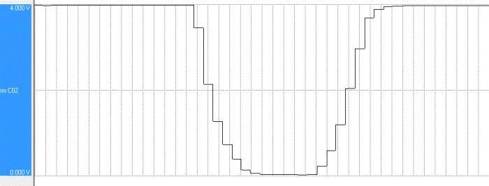
Some time ago, I had done some preliminary attempts at closed loop control, and had concluded that speed control was more responsive and would be a better choice. However, with what I’ve learned this week, I needed to revisit that choice. Here are some open loop response charts, showing the dancer position (input variable) plotted along with the output variable (speed or torque command):

Speed control:


Torque control:


It turns out that torque changes are slightly faster for the DC drive to process, with deadtime of 130 ms, while speed control changes have a deadtime more like 220 ms. This makes sense with the drive’s block diagram, since speed control is the outer loop feeding into a current control inner loop. (Although it isn’t pictured, I did check to make sure that open loop changes in either direction resulted in similar deadtimes).

I think that when I was attempting this some time ago without regard for the analog input module data freshness, I had found torque control less effective since the effective PID rate was so much longer than the process lag (2.6X), it was always overshooting or de-tuned so strongly that it would barely respond at all. Even the speed control wasn’t as tight as I expected, leading to the troubleshooting earlier this week.

Anyway, with the new analog input module at 11 ms freshness, I can set the PID rate to be at 1/5th to 1/3rd the torque control deadtime, which is much more conducive to tight control. I’m feeling much better about this now than I was a few days ago.

Quick update… with the SNAP-AIMA module instead of the SNAP-AIMA-8, the PID response time has dropped to an average of 19 ms (ranging from 10 ms to 42 ms). I’ll probably set the PID scan rate to 25 ms, usually getting fresh data and nearly guaranteeing that at least every other reading will be fresh (104 out of 121 logged steps were 21 ms or less).