I need help with cascading a PID loop. I have a double boiler type system where I have two polypropylene tanks, one inside the other. The outer tank has the heater installed and uses water. The temperature in this tank cannot rise above 160 degrees F. The inner tank is heated by the temperature from the outer tank. The inner tank temperature is our main priority. I am using 2 temperature probes, one in each tank. I have read a little on cascade controls, but don’t fully know how to do it with the Opto22 R2.
Thanks,
Steve
Hi Steve,
What are you using to control the heating mechanism? (For example, do you have a digital output module that will turn a heater on/off as the result of a PID calculation … or an analog output module that will increase the heat slowly?) Also, to be clear, when you say the outer tank “cannot rise above 160 degrees F” I’m guessing you don’t mean that it’s not physically possible, but rather it shall not - must not - “boss will be mad if I let it get above 160” type situation?
If you’ve not already seen our PID Tutorial, the documentation that goes with it is excellent, even better if you have a [URL=“http://www.opto22.com/site/pr_details.aspx?cid=1&item=SNAP-PACLC”]SNAP PAC Learning Center to use with the included strategy.
-OptoMary
Thanks for the response. I am using a 4 to 20 ma output module driving a Watlow controller, so I can vary the voltage to the heating element. The outside tank temperature cannot rise above 160 degrees per the manufactures recommendations. It is just below the maximum operating temperature of the plastic. I want to control the inner tank temperature to 115 degrees by heating the outer tank. There will be a lag in the control system, so I need to allow for that.
Steve
I’m no PID expert so I’d be very interested in what those w/loads of PID experience (I know you’re out there!) have to say about this one, perhaps even my buddy Ben who did this PID Webinar (click here for link to recording).
I do know that our 4-20 modules are lovely in that they can be scaled. I suspect it might not be as simple as scaling your heater’s analog output point to the degrees F temp that corresponds to that mA value (especially given the lag time you mention).
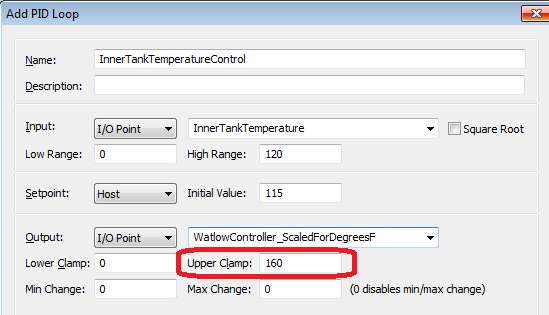
But perhaps you could set the PID output’s “Upper Clamp” to something that would be low enough to keep that tank from reaching 160. If during tuning the PID you’re still not 100% sure what that value is, you could add a loop in a chart to adjust that Upper Clamp value down if you see that the temperature reading of that outer tank is getting too high (using the “Set PID Output High Clamp” command).
But that’s just using one loop rather than the cascading loops you mention, so perhaps I’m barking up the wrong tree.
Thoughts? PID pros out there?
-OptoMary
i lay no claim to being a PID expert or guru (and never used cascading PIDs), but fwiw it sounds like you need a PID loop to control the outer tank to ensure it doesn’t heat up above 160deg and a PID loop enable/disable function to control the inner tank temperature.
I’m not sure of the parameters the inner tank temperature has to be within (+/- some temperature around inner tank setpoint) but with a PID on the outer tank you can ensure that the temperature will not rise above the high temperature specified in the PID loop by setting the input high range to the max permissible temperature allowed (eg say 150deg) and ticking the checkbox ‘force output when input is out of range’ and setting the high value to something like 20%. this will protect the outer tank and you could do some simple logic that when the inner tank temperature reaches its setpoint, you could either disable the outer tank PID and set the output to 0 (or a nominal value) or set the PID to manual and let it hang and set to 0 when it reaches a deadband value. when the temperature of the inner tank drops below a lower deadband temperature it enables the outer tank PID loop again.
Given the lag in the PID loop, it would be awfully slow and would take a bit of tuning to get all the parameters right. it might even require some defined output values for the PID loop at certain conditions, like cold start, min-load, max-load etc…
I hope this helps
Nick
Steve
Im no pid expert or guru either but having now thought about it for a bit, I think what would work would be to set up a PID loop for the outer tank with the set point being the PID output of the inner tank (cascading pid?).
To do this you will have to create a dummy output point on the I/O unit scaled from say 0 to 150. This will be the output point for the inner tank pid loop. The inner tank temp sensor will be the input for the inner tank pid and the set point will be 110deg. The pid loop min/max range would be set the same as the dummy output point.
When configuring the outer tank pid loop, the set point would be set to I/O and pointed to the dummy output point. You could set the PID input upper value to 150deg and by setting the force output when out of range to a nominal value would ensure the outer tank would be protected. The input for this pid would be the outer tank sensor and the output would be the watlow controller.
Then it would be a matter of tuning. As the inner tank gets hotter the set point of the outer tank decreases (this would indicate a - p value) therefore backing off the heating element. If the inner tank is cool, the output would increase therefore increasing the set point of the outer PID loop. It would be a fun tuning experience.
Outer tank control would have to be pretty responsive to cater for the set point changes, and the inner PID would have to be slowish to ensure there are no massive output changes (resulting in set point changes in the outer tank pid loop). It may be the case that the dummy output point might have to be scaled between say 100deg and 150deg or the inner PID loop max output change be limited to something like 5 or 10 to ensure the output cannot go from min to max in a short period of time causing the outer tank pid to swing massively.
If I was going to perform this I’d probably tune the outer pid loop first and make sure it is very snappy and responds well to setpont changes. Then I’d start with a slow pid loop on the inner tank working up to some acceptable tuning values. if the inner loop gets hard to tune (causing problems wit the outer tank pid loop), I’d probably look at trying rescaling the output of the inner tank pid or restricting the max output change of the outer tank pid. At some point you should be able to get them in sync.
Bear in mind too that if you don’t have the room on the IO unit for a dummy output point, you can set the output of the inner tank pid to host and the set point of the outer tank to host. This would then involve coding in some commands to read the inner tank output into the set point of the outer tank. If the IO is remote (ie an eb or sb brain) then the pid’s would not work autonomously as they would rely on commands from the strategy to perform their tasks.
I hope this makes sense (it did to me when i was thinking it…)
Nick
Steve,
I think Nick explained a very good process for you to follow.
I agree that your first task should be to set up a PID control for your outer tank that will respond quickly to setpoint changes and track as well as possible. I am envisioning your two tanks creating a relatively small annulus between them. Response will depend on water volume, heater power, insulation, water mixing, etc. Limiting the setpoint of this loop to something below the 160 limit for the tank material is a good idea. Account for overshoot.
Once you have this loop tuned to your satisfaction, then create a second PID loop. Its output will be scaled to be the setpoint beint input into the actual heater control loop. So rather than directly controlling the heater, it will control the heater setpoint. Kind of like you feeling cold at home. You go adjust the thermostat that directly controls your furnace. You don’t actively control the furnace, rather you adjust it’s setpoint controller.
Good Luck