Persistent Timers

Persistent timers in PAC Control.
Lets not get any of us long term PAC Control users triggered by talking about how even after all these years PAC Control still does not maintain timer values between downloads or reboots….
But rather let’s talk about why you might want such a feature.

Use case #1.

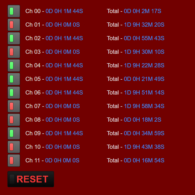
Maintenance. Let’s say you have a pump house that needs bearings and seals replaced before they fail, so you need to track the total hours any given pump has accumulated.
When you start the pump the first time after replacing all those parts, you want to start counting from zero the days, hours and minutes it’s been running.
When the pump turns off, the timer pauses, when it starts again, the timer resumes from the timer value it paused on…
At midnight, you move the current timer into a different table that keeps track of total running time over the weeks and months, after moving the day’s run time to that table, you reset the daily run timer.

Of course all the timers and tables survive a download or a controller power cycle.

Use case #2.

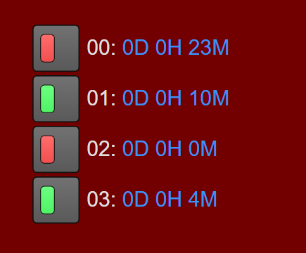
State timer. You want to know how long a digital (or variable) input or output has been turned on and when it changes state you want the timer to reset back to zero and start timing again.
This way in groov View you can quickly see how long a device has been on or how long it’s been off.
Of course the timers survive a download or a controller power cycle.

As far as making persistent timer code goes, both use cases end up being rather different from each other. The first requires keeping track of each pause and resume with a master save function and the second requires a hard stop/reset/start methodology.

The trick to all this is to not actually use any of the PAC Control timers. Up timers get reset back to zero when they are loaded with a value and down timers don’t keep track of long running processes.
Rather, you need to use actual date/time values and keep track of when different events happened in real time which are then converted to seconds and those seconds are kept track of……

In both cases, heavy use of persistent tables and variables is the only way to keep track of time through a controller reboot or strategy download.

All this was beyond my skill set, so I tossed it over the cubicle wall to @torchard. (As you do).

1 Like

To answer that first use case and get table of accumulated uptimers, we’ll first need to establish some variables that will not be reset if there’s a download or power cycle, and it also can’t roll-over if the number becomes too big, so persistent 64-bit integers to the rescue. To make this work for multiple pumps (or whatever you want to track) as easily as possible I’ve used tables instead of single variables, so this can scale up to all 32 channels on a digital module, or up to 32 timers across as many modules as you want. (You can always change this number by modifying the table tags.)

The key thing here is to NOT rely on perfect timing of a delayed control loop, and instead use a timestamp to determine elapsed time. A big benefit of using the current time is that it’s not “reset” when the system is powered off or restarted. Also, unlike seconds since midnight timestamps work over weeks or even months, and can rollover whenever the user chooses rather than at a specific time (like midnight for example).
So, given all that the logic flow is: establish a baseline timestamp (seconds since the year 2000), then loop through tables to determine if the channel is turned on, and if it is on accumulate the elapsed time since it was last updated, and convert that elapsed time into a human readable string with days, hours, minutes, and seconds. If the channel is turned off don’t do anything.
Separately to that is the store-and-reset, where a variable will determine when the run is over – whether that’s a shift cycle, a day, a week, or whatever makes sense for your application. Get the accumulated time for this run when that flag is flipped on, add that to a grand total, and finally make that a readable string. So if the run time is 13 hours at the end of a day, and the grand total was 22, it’ll be updated to 35 hours.

So, with that rough explanation out of the way, what does the user actually need to worry about?
The most critical variables are timer string tables, both for the run and the total, the int32 table for the current state, and the reset flag. The current state should be mapped to the IO being timed, and the current run can be seen in the display string table (determined by the accumulated time integer table) and the grand total can be seen in the display total string table (determined by the total time integer table), and finally the reset is just a 1 or 0 integer to reset the current run.
The count should be set to the number of channels (max 32), and the rest of the variables are just for internal use in the background calculations: current time, elapsed time, loop index, trash, temporary string, date/time table, previous state table, and saved timestamp table.

Here’s the chart brought together in an example groov View page, using toggle buttons to simulate 12 inputs:

The far left buttons are tied to the timer_currentState tags, the left column of timer_display is the display time, and the right total column is timer_displayTotal. Finally, the reset button is of course timer_reset to add the current timers to the total time and reset them back to zero for the next run.

You can find the chart export attached to this post, so feel free to download that and try it yourself! Hopefully it does what you’re looking for, if not feel free to modify it for yourself and drop a line in the thread below to let us know what your application is.

And as always, happy timing!

UpTimeTable_Chart.zip (2.2 KB)

1 Like

For the second use case I’ll take a similar approach, saving timestamps in seconds to a table of thirty two 64-bit integers, but in this case there’s no need to have a save accumulated time and save a “grand total” – it’s just elapsed time since the last state change. Given that this solution can be simplified a little by just saving the timestamp for the last event, whether that’s going from on to off, or off to on, and then convert the elapsed time between that event and the current timestamp into a human-readable string.

That also means there are less user-facing data points to interact with: just the current state of the timers that will likely be mapped to the IO you want to track, and the timer_display string table that shows the elapsed time. It is of course necessary to save persistent timestamps in seconds as well as the previous previous state so that the reset can be triggered whenever the state toggles, but the rest of the tags are just used in the background to track time and manage the table loop.

All that comes together into a full table that tracks up to 32 timers that reset and start counting up again whenever the current state switches.

Here you can see timer 0 was turned off 23 minutes ago, 1 was turned on 10 minutes ago, 2 was just turned off, and 3 has been turned on for 4 minutes:
image
Each of these will persist with a strategy download or power cycle – and will include that time when it comes back online. For example if the device is powered off for 10 minutes, when it comes back online, timer zero would read 0D 0H 33M since it is based off of a timestamp, not an uptimer.

As with the first example you can import this chart and try it yourself using this download link:
TimerTable.zip (2.0 KB)

1 Like

Terry while I like the idea of using internal clock timestamps to record the passage of time, I don’t think timestamps are the best approach to maintain totals. Using timestamps (which I have done) are a good way to know how long the system has been down (controller or PACControl not running).

The issue with timestamps is that the internal clock is not always tied to a Network Time Server.
Plus changes to timebase(PACDisplay update to PC time, Groov Manage time changes, daylights saving time, etc.) or clock drifting over time (no NPT) could skew results.

My suggestion is to use the Uptimer (which times in seconds) as your timebase (its fairly accurate in the short term) and integrate / add (how much time has elapsed since you last checked) into a persistent variable. This will provide a fairly accurate timebase which will be maintained when the system is shutdown.

I’ve done this with just a persistent float but rounding errors as the float increases will decrease accuracy.

To maintain accuracy, using a I32 and/or I64 for both time and process integration (using math not a PID) is more accurate but you will need to take into account fraction of a second which requires adding a persistent float variable to cover fractional seconds.

A cleaner approach is to use a Persistent Float Table to record SEC / MIN / HOURS (or GALs, 100s of GALs, 1000s of Gals if integrating flow, etc.). Same overall idea (using an uptimer - which could also be used as the timebase for multiple timers) that adds the elapsed time since it was last read into the seconds index and increment Minutes every time we have 60 or more seconds. Do the same with minutes into hours, etc.

For example: an uptimer is being read on a loop every 50msec, we read/record the elapsed time (say .05012345), reset the timer, and add the elapsed (assuming conditions are enabled) into our Seconds Index (current value + .05012345), repeat. When seconds increase to 60 or more then increment Minutes by 1 and subtract 60 from seconds (leaving fractional in seconds index). Same idea with hours, days, months, etc. however you want to break out your time (though hours/minutes/seconds would have to get very large to loose accuracy).

Since we never let the seconds float get too big rounding errors are minimized (or the highs and lows cancel each other out). However if this is a concerned then setting up to record a smaller timebase (ie. every 100msec) is an option.

Thanks for sharing the feedback @Lou_Bertha

I should mention in @torchard ‘defense’ he coded up a specific customer use case that required the timer to continue while the controller is powered off.
In this case the outputs (water pumps) continued to run while the controller was offline in anyway.
Once the controller came back up, the operator would need to know how long that day the pumps were running.
This was hinted at in my use case preamble.

Your point of time jitter is well taken.

Have you a code sample that uses your up-timer method?

Here is a sample of how I would approach this. Units are stored in milliseconds, so I’ve included the math for the formatting logic too. (Should be an HMI concern, if the HMI is capable).

nnUpTime_ms is persistent - could easily do an array as well to store the up times for various things. The 64-bit integer will overflow sometime after 292,277,024 years.

//Start timer if it isn't running
if(utUpTime == 0.0) then
  StartTimer(utUpTime);
endif

//Get the timers value and restart it
fTimerValue = GetRestartTimer(utUpTime);
nTimerMs = fTimerValue * 1000.0;

//Add to the up time in milliseconds
//nnUpTime_ms is a persistent 64 bit integer
nnUpTime_ms = nnUpTime_ms + nTimerMs;


//Format for display
nUpTimeDays = nnUpTime_ms / 86400000;
nUpTimeHours = (nnUpTime_ms - (nUpTimeDays * 86400000i64)) / 3600000;
nUpTimeMinutes = (nnUpTime_ms - (nUpTimeDays * 86400000i64) - (nUpTimeHours * 3600000)) / 60000;
2 Likes

Code Sample - the Float Table is Persistent

MR_LOOP_TIME is captured time between cycles - note I’m also using it for other processes:
MR_LOOP_TIME = MR_LOOP_TIMER;

if (MR_LOOP_TIME <= 0) then
MR_LOOP_TIME = .001;
endif

SetUpTimerTarget(1,MR_LOOP_TIMER);
StartTimer(MR_LOOP_TIMER);

///////TOTAL OPERATIONAL TIME
MR_TIME_TOTAL_TABLE[0] = MR_TIME_TOTAL_TABLE[0] + MR_LOOP_TIME;

////SEC TO MINUTES
WHILE (MR_TIME_TOTAL_TABLE[0] >= 60)
MR_TIME_TOTAL_TABLE[1] = MR_TIME_TOTAL_TABLE[1] + 1;
MR_TIME_TOTAL_TABLE[0] = MR_TIME_TOTAL_TABLE[0] - 60;
WEND

////MINUTES TO HOURS
WHILE (MR_TIME_TOTAL_TABLE[1] >= 60)
MR_TIME_TOTAL_TABLE[2] = MR_TIME_TOTAL_TABLE[2] + 1;
MR_TIME_TOTAL_TABLE[1] = MR_TIME_TOTAL_TABLE[1] - 60;
WEND

/////HOUR
MR_TIME_TOTAL_HR = (MR_TIME_TOTAL_TABLE[0] / 3600) + (MR_TIME_TOTAL_TABLE[1] / 60) + (MR_TIME_TOTAL_TABLE[2] * 1);

Of course you can easy display HRs MINs SECs or calculate however you would like. Found that tables made life easier and I could scale up if needed.

@philip - I did something similar converting to msec in the past but was worried that I was shaving off fraction of msec which is why I always had a float capturing this faction (I know, I’m nuts). Figured I’m eking out more accuracy over time. Of course I’m assuming that the internal timer value has sub-msec accuracy. This is why we all love geeking out over this stuff.

2 Likes

It’s always good to think about all the edge cases, so nope, you’re not nuts. The nice thing about an int64 is it is big - we could use units of uSec and still have almost 300,000 years of runtime without overflow if you were concerned about the fractions of a msec.

@Lou_Bertha and @philip thanks a TON guys for the code examples.
This is a fantastic thread of different ways to handle persistent timers in PAC Control!

I use up timer and a persistent float:
tmru
tmru_Save

I initialize up timer using this code:

StartTimer(tmru);
SetUpTimerTarget(1.0,tmru);
PauseTimer(tmru);

On any part of the program, I use the following code to continue and pause:

ContinueTimer(tmru);
PauseTimer(tmru);

I have a chart that runs 100ms loop and do the following:

if(HasUpTimerReachedTargetTime(tmru))then
    tmru_Save = tmru_Save + tmru;    
    tmru = 1;  // re-start from zero and set target to 1
endif

In the end tmru_Save holds the elapse time in seconds even if strategy is restarted.

Let me know some flaws in this code strategy.
In this case Up timer can hold 4.6x10^15 sec. Thats 48 billion days. 130 Million Years. Is this right?
Float can hold 3.4x10^38.
So we are good.
Edit: Max limit is 16,777,220 sec or 194 days for float to accurately hold additional small increment.
As Lou Pointed below and above.

I just worry about racing condition, consider two charts.
One chart (will start timer):

if(HasUpTimerReachedTargetTime(tmru))then
    tmru_Save = tmru_Save + tmru;    
    tmru = 1;  // re-start from zero and set target to 1
endif

on the other chart (will pause timer):

PauseTimer(tmru);

Float Rounding Errors (IEEE 32bit Float) will limit how much can be saved.
As your number gets larger the smaller increment will be ignored (was noted earlier in this thread).
Suggest you implement per the examples above (which avoid this limitation).

I was going to point to Wikipedia but Opto has a very good overview of 32bit floats: