Peer-to-Peer - how do YOU do it?

I’ve been looking through various requests for Advanced Training and the requested topics are wide-ranging. One topic that comes up often is Peer-to-Peer where devices share information with each other.

When the devices are controllers, the “how” varies from the older Factory Floor controllers (where peer-to-peer was much trickier, via TCP), to the recommended usage of our Scratch Pad commands in PAC Control as described in Chapter 10 of form 1700.

There’s also the option of doing Mirrored I/O (click that link to see a recent description in OptoNews), if you’re sharing data between two brains.

Any of you OptoForum users out there doing some form of sharing data between Opto 22 devices, either using the methods mentioned above, or something different?

Do share!

Thanks,
Mary

Mary,

Our first attack at this topic was pretty crude, but it got the job done so well, that we left it in place for some years.
(If I get some time we can dig into some of the more advanced ways we did this).

In a nut shell we just ran a chart every three seconds and it just wrote the data into the scratch pad of the other unit (or itself depending on what we needed from that peer).
Here is how it looks from the outside;


In each block was the appropriate command “Set I/O Unit Scratch Pad Float Element”.
Floats, ints and strings… as needed…
We just had to keep track of what index had what values in it and make sure we did not double up on the index numbers.
Not all that hard to do in the comments / text.

At the other end, we just read that scratch pad index, and hey presto, peer to peer.

So as you can see it was really simple, but it got the job done.

Those commands made life soooooo much easier than when first tried it when the M4SENET-100 cards first came out and none of those commands existed in Factory Floor…but lets not drag up past horror stories (My first attempt at that chart bricked the LCM4 controller about 4-6 times before I figured out what I was doing wrong. The only way to get it back was to do a fail safe boot loader recovery…but I said that we were not going to drag up those old war stories!).

So, yeah, peer-to-peer, how you all doing it?

Ben.

Here’s the latest chapter to help make peer-to-peer even better–now your data can be stored in either:

  1. The "local" scratch pad area
  2. Another I/O Unit's scratch pad area
  3. Your PC running OptoMMP Server (New & very exciting)
FYI - to allow my R1 to "see" this "Generic OptoMMP Device" running on my Windows 7 PC, I needed to turn off the Domain piece in my Windows Firewall.

Check this out: neat-o!


Download this nifty server now: OptoMMP Server.
-OptoMary

Here’s another method of doing peer-to-peer, or connecting a groov to a Factory Floor controller!
http://www.opto22.com/community/showthread.php?t=491

Hi I am new to the Opto Product. Is there any more info on setting up the Scratch pad Peer-to-Peer communications?
I have read the 1700 chapter 10 which has good over view, 1704 Pg.95 but i don’t have configuration file, as i worked from PAC control, and 1595 chapter 3 also a good description on how it will work when i get it set up.
I have tried to us the command but i don’t think i have the I/O Unit of the type Generic OptoMMP Device.
-Jon

Hi lowbank,

Welcome to the OptoForums!

The commands you’d use for that method of doing peer-to-peer do not require a particular I/O Unit type (should work with all of them).

If you don’t yet have one configured for the “peer” you want to communicate with, just add one with the IP address of your peer controller and choose that Generic OptoMMP Device for the type.

Also, don’t forget our product support is FREE! and they have lots of experience with this Scratch Pad method of doing peer-to-peer.

Cheers,
OptoMary

HI OptoMary
Thanks for the welcome.
I am setting up peer-to-peer between SNAP-PAC-R2’s. So I don’t need the Generic OptoMMP Device is this right? If so where do i define the scratch pad area. Also when i add a “Set I/O Unit Scratch Pad float Element” command. I have no “Index” Variable to use or “Put Status in” Variable to Put it in. I can change the value of the scratch pad address in PAC Manager. but cant see how to connect this to my strategy.
-Jon

Hi lowbank,

I can see you are some of the way there, so forgive me for helping those that follow in the future and go back to basics.
Lets start at the start for doing peer to peer…

In controller 1, set controller 2’s IP address as an IO unit. (A real IO unit or generic, it does not matter for scratch pad use).
In controller 2, set controller 1’s IP address as an IO unit. (A real IO unit or generic, it does not matter for scratch pad use).
(Dont worry about modules, you just need them for their scratchpad areas).
In both strategies, setup each controller in the IO enabler chart so if they go off line, they will get back online automatically.

Ok, so now that each one can see the other, we are ready for the strategy to exchange data.

Open up doc 1703. You can do this from PAC Control, click on Help->Manuals-> Commands quick reference.
Go to page 5. It has the ‘I/O Unit- Scratch Pad’ command section.

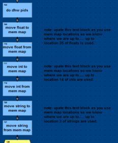
As an example; Controller 1 will issue the command ‘Set I/O Unit Scratch Pad Float Element’ every (say) second.
When you pull up the command, you will see how it works.
You will be setting the I/O unit to be Controller 2. The index you will need to keep track of (perhaps make 0-99 controller 1 and 100-199 to be controller 2, just a thought) so you don’t use the same index twice.
It will come from a float variable (or an int if you use the int version of the command, or a string if you use the string version).
Put the status in a trash variable if you don’t care if it gets written to the other controller or not, or in a variable that you do a check of if you do care.
Done.
That’s all it takes for controller 1 to write a float var to controller 2.

In controller 2 you will have a chart that uses the command ‘Get I/O Unit Scratch Pad Float Element’, only here it will read it from itself, this way it will read the value that controller 1 wrote.
Done. The loop is complete.
Controller 1 writes it to controller 2, controller 2 reads it.

Reverse the whole thing for controller 2 to write to controller 1 and controller 1 reading itself to get the value.

Note that Opto has already defined the scratch pad area for you.
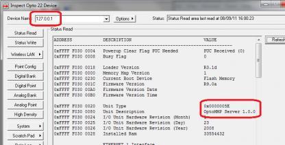
No better way to do this than to open up Pac Manager and click on Tools->Inspect.
Enter the IP address of either controller 1 or controller 2.
Once that data comes up, on the menu on the left, click on ‘Scratch Pad - > Floats’.
There you can see the whole scratch pad area, and the index for each element.
If your strategy is running those commands, you will see data in the matching elements.

Lets know how you get on.

HI Ben
Thanks for that simpler then I thought. One Question. Is it better to write to the remote sites like you have in the above example. Or if you write to the local Scratch pad and the remote site retrieves the data over the net work. does this make any difference? Not sure if you will call this of topic, But if the remote site is disconnected and I have a groov box watching a Variable from the remote site in the local Scratch pad what is a good way to alert users of groov that the value on groov is not getting updated because the comms is down?

Attached diagram of my project


Gudday lowbank,

Thanks for the diagram, always helps when you have a big picture.

Regarding peer to peer it does not matter if you push or pull (in my experience)… Either way you need to know the data validity and be able to handle old stale data. If you do it at the server (central) or at the client (remote) really does not make much difference.

Regarding stale data, there are a few different ways to tackle it…
What we did at the hospital was to make index 0 be the controllers ‘seconds since midnight’.
All the controllers had time sync charts in them, so they were all roughly in sync.
When ever we did any peer to peer data work, we always looked at the source time, if it was within about 10 seconds of the controllers time, we knew we were working with good data.
If we were more than 10 seconds out, then we considered it old and handled it accordingly (up to you to decide what that means for your process).

You could put a counter in index 0 and every write increments it. The client reads the count and compares it to the last time it read the data.

You could put a counter in index 0 and every write increments it. The client could write 0 to index 0 when it does the read.

Im sure you get the idea. The key is to have some other bit of data that shows the age of the data being read/written.
Once you have that bit of data, its trivial to attach it to a groov gadget. (Have a status page or put said gadget on every page - or both).

Lets know if any of that is clear as mud.

Cheers,

Ben.

P.S Sorry, cant help myself… Aussie Aussie Aussie!!!

Lowbank, on [B]all[/B] remote apps, you have to make absolutely sure to make yourself a trimmed down version of the IO enabler chart. Without this, you will have problems doing anything other than hardwired Ethernet. I believe the the scratch pad command returns a status var but I don’t rely on that, use the status vars of the IO Enabler chart and you will be in good shape. I have a 4 site well system running right now over wifi 5.8 and it runs absolutely flawless, as if hard wired, but only because it has the enabler chart. Even though i have near perfect communication at 30 meg plus through put, I can assure you that it would probably still disconnect the peer connection once and a while and that is a problem since it will not reconnect on it’s own.

Thanks for the tips Ben.
So with the groov interface i can’t blank out a gadget that is not updating but i can make another gadget that lets me know there is a problem. Or maybe where a gadget is displaying a variable I could change the gadget variable to say 999 if problem with Peer to Peer to alert user of problem. I was also thinking of having a one digit count in corner of screens that goes from 0-9 as a hart beat.if this was generated by the remote site it would give you a ongoing indication of link health.
Cheers
Lowbank.

I would, in the strategy, have a single int32 that is 1 if all is good (online) and 0 (offline) if the data is stale.
In groov, I would hook this variable to an LED, green if 1, red if 0.
Stop and go. Online, Offline. Simple, clear bold.
Sure, chuck a counter in small text under that if you like that give more info… and there, I would attached a date time stamp to that first int32 in the strategy.
In groov then I would have the LED clearly showing remote status, and under that, a ‘last heard’ time stamp. It would update with every remote read, so it would be roughly the current time. When the LED turns red, the time stops updating, that way you can show the user the status and the last time the remote site was heard from. (Other wise, you know the very first thing they are going to ask is ‘when did it go offline’?).

That’s just my quick take on it. Your process/workflow/customer/expectations may require a different approach.

Hey Ben.
Where did you get the [I] ‘milliseconds since midnight’. [/I]I could really use that on an R1 or R2.
Thanks,
Norm

[I][/I]

Hi Norm,

You won’t find a “milliseconds since midnight” command in PAC Control, but you can programmatically pull that value from your R1/R2’s mem map using a PAC Control command. Check out this post for an OptoScript example of how to do that. Let me know if you’d rather have an Action Block example for the same thing.

Also remember to use an int 64 value to store that in so you don’t have to worry about running out of bits!

-OptoMary

Oops, forgive me, the example I just linked to was milliseconds since [I]powerup[/I], not [I]midnight[/I].
Can you give us more context for the “big picture” you’re trying to solve here? Probably a couple of different ways to solve this w/timers, etc. Which one is best will depend on your overall goal…

The Opto script goes like this;
TIME_In_SECONDS = GetSecondsSinceMidnight();

As far as I know, there is no milliseconds available.

Thanks Ben, I read in one of your posts above, that you had used milliseconds since midnight at the hospital so I got all excited.
I had never seen it anywhere so was hoping it was an undocumented MM location.

Thanks Mary,
Timers wont work for this. I was looking for a way to accurately sync time events on multiple R1’s. A common reference point would need to be referenced. Midnight would make that work for me. Especially since we have the nice new NTP time sync functions. It is odd that we have ms since reset but not midnight. A controllers reset time is not based on any standard reference where midnight is. If ms since reset was changed to ms since midnight (hint, hint), integrators’ would have a way to better determine when an event occurred on large geographically diverse installations.

So you’re saying syncing to the nearest second (vs. millisecond) isn’t accurate enough?

We CAN’T actually change the ms since powerup to ms since midnight that would mess up those people currently using the ms since powerup. We might be able to add something else, but probably not something w/ms accuracy.

However, I’m not clear on why you wouldn’t just use those nice new NTP time sync functions on each of your R1s? Just phone the mothership every day or perhaps every hour (not too often so as not to get yourself banned from phoning the NTP mothership). That would avoid the few seconds of daily drift you’d normally get on each R1, and make sure they’re relatively sync’d.