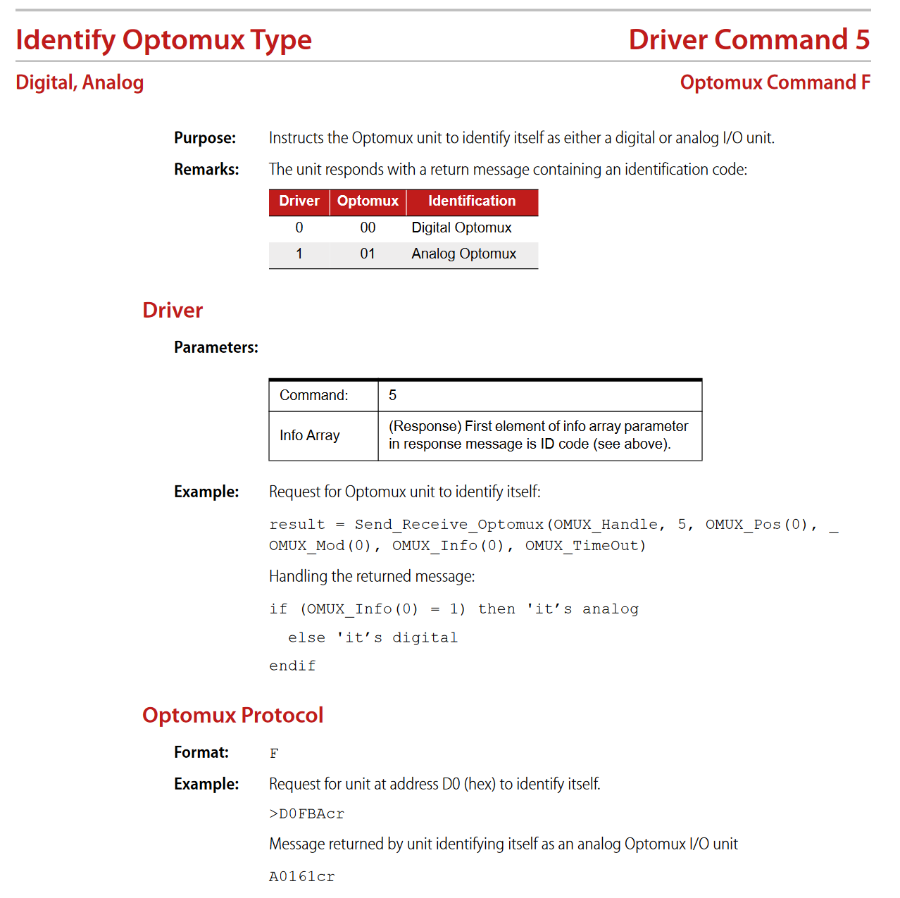
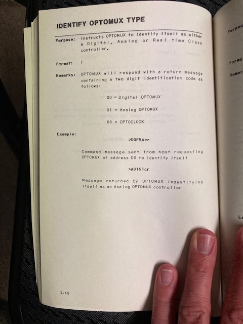
In looking through the OptoMux User Manuals for the B1 Digital Brain (3rd Ed, 1984) and the B2 Analog Brain (3rd Ed, 1984), I saw under the IDENTIFY OPTOMUX TYPE command (F) that I can expect one of three 2 digit codes on a successful reply:
00 - Digital OptoMux
01 - Analog OptoMux
08 - OptoClock (real time clock)
I understand the hardware referred to in this post is old and obsolete, but they are still rocking and rolling for me. In writing an application for a friend that controls a model train layout, I saw the above and my curiosity was spiked.
So, can anyone describe the OptoClock from a hardware perspective?
How did it integrate and support the OptoMux hardware?
I believe these manuals pre-date the document number system Opto22 utilizes. I will check tonight and repost, but I see nothing on the book cover nor inside page (I can send/upload these if you are curious).
Edit: Attached is photo of Identify command showing the three responses.
Thank you again for the welcome, and also the reply!
I have (6) B1s and (4) B2s, and they all reply 00 or 01 correctly in response to the Identify command. I never saw the 08 response, but that is because I do not have the hardware.
I started this as I wanted to learn about the OptoClock hardware, OptoMux commands it supported, and how it integrated with the rest of the OptoMux hardware.
As a follow up, I found in the OptoMux Digital User Manual, 4th Edition, 1984, the following on the OptoClock:
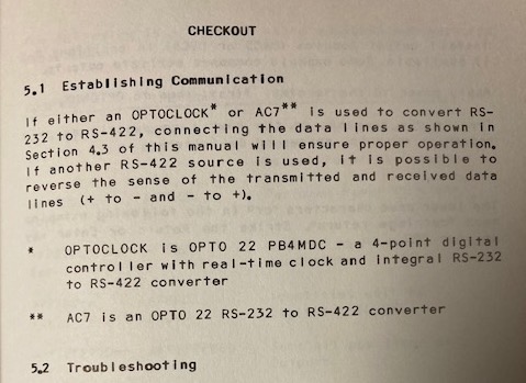
“OPTOCLOCK is OPTO 22 PB4MDC - a 4-point digital controller with a real-time clock and integral RS-232 to RS-422 converter.”
Thus, I am going to conclude that the OptoClock is combination of the AC7 (RS-232 to RS-422 converter), a B1/PB4H combo, and a real-time clock. Given that conclusion, I will go to say that the OptoClock likely supports the same OptoMux commands as the B1, but also something for setting and reading the real-time clock.
From the OptoMux Analog User Manual, 3rd Edition, 1984, in the Introduction section, the OptoMux family is defined as the following devices:
PB4MD -> 4-point digital controller
PB4MDS -> 4-point digital controller with onboard power supply
PB16MD -> 16-point digital controller
PB16MDS -> 16-point digital controller with onboard power supply
PB4MDC -> 4-point digital OptoClock
PB4MA -> 4-point analog controller
PB16MA -> 16-point analog controller