Error -216 in the PAC Control Modbus kit is a Timeout Error.
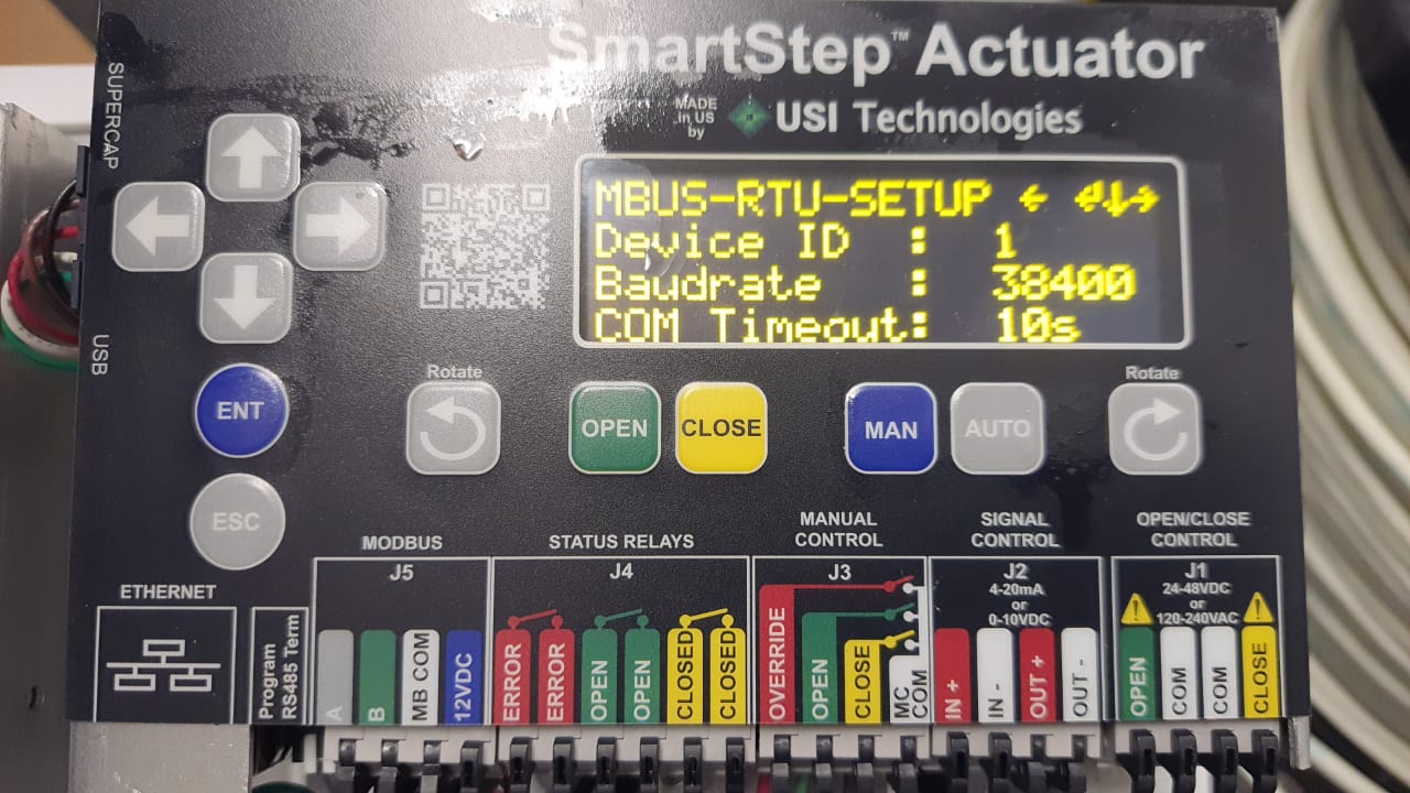
The SmartStep device seems to not reply in time or at all. Does the Slave device have LED indicators for the serial interface? If so, can you see the Receive or Transmit LED blink?
A couple of things that we run into on issues like this (some are obvious but I always ask):
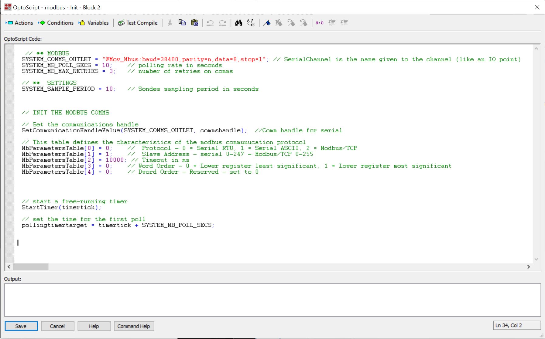
Are you using RS232 or RS485 (2 wire or 4 wire) ? Make sure your serial port setup matches the field device and RS232 TX/RX wires cross.
Double check the Field Device parity, data bits, and stop bits.
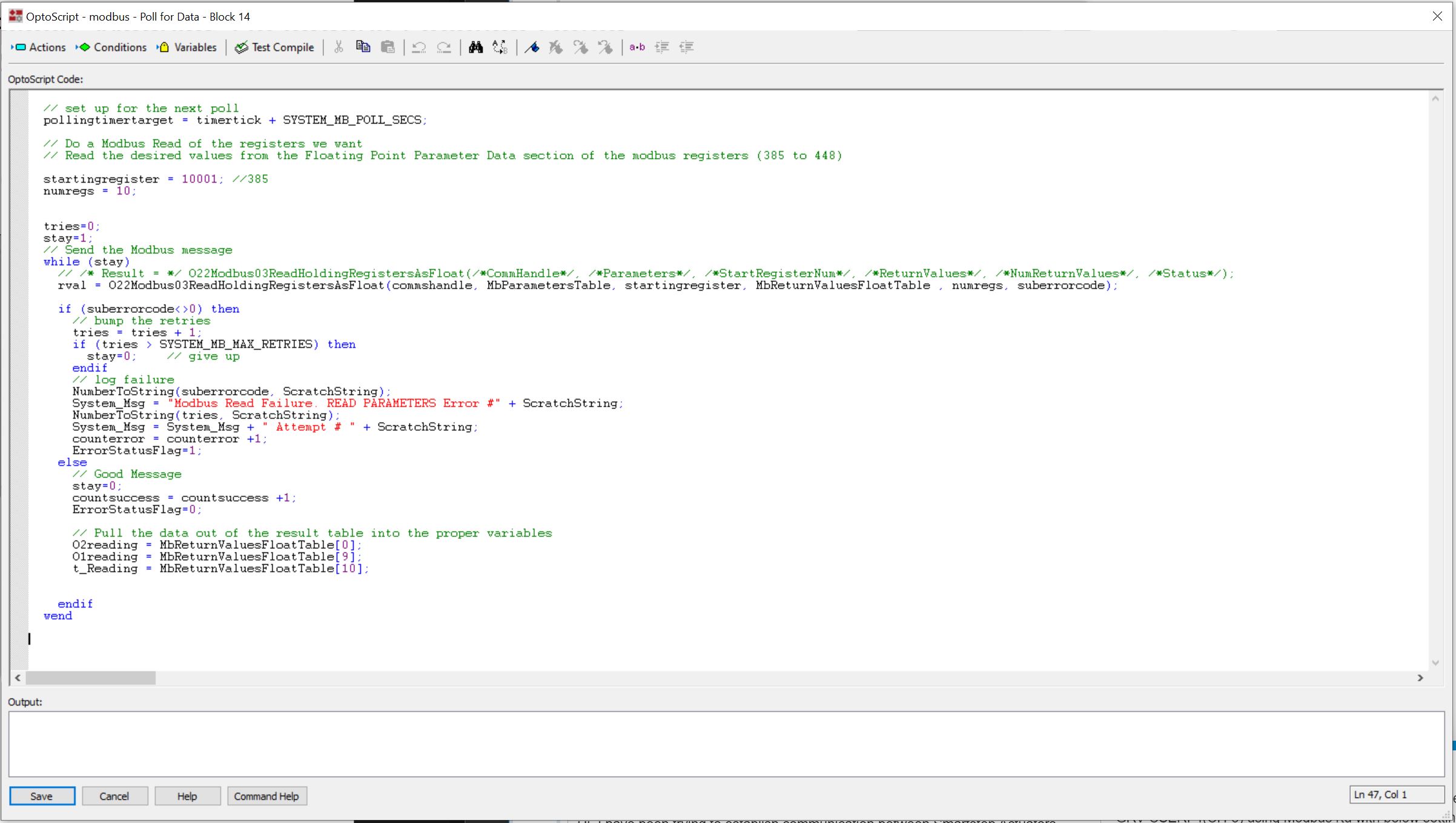
Try testing by reading only 1 register: 10001 then 10002, etc. to see if you get communications. We have run into system that have registers that do not respond (not sure why) and had to read individual or smaller groups (note: reading 10 items should not be an issue).
Register 10001 - you are setup to read holding registers but when I see 10001 I think its a Discrete Input at register 1 (while a register of 40001 is a Holding register at register 1). You shouldn’t get a timeout error but like the scenario mentioned above about the field device not responding outside what its setup to look at, this could be a factor. Something to verify.
Looking at the manual https://www.update-systems.com/download/smartstep-full-user-guide.pdf for the smartstep actuator (I think it is the same as what you are using), it looks like you are wanting to read the coils 10001 to 10010. @Lou_Bertha is correct in that you need to be using the modbus kit subroutine to read “discrete inputs” for that.
I don’t see floats in the register map for that device, so you would not use the subroutine you are currently using. However, the device should return a modbus error, not a timeout, so this may not be your only issue - but it is not unheard of for a modbus device to just not respond to invalid requests.
On your starting register, you need to drop the leading 10000 or 30000 or 40000 - that is an old modicon way of addressing that isn’t used in the current modbus spec (like 2007). The manual also gives the true “address”, though note that the Opto modbus kit uses registers, so you will add 1 to the address that is given. So to read what is listed as 10001, you would simply use register 1 in your code.
For wiring, confirm that the A terminal is connected to Terminal 23 (Tx/Rx-) and the B terminal to terminal 22 (Tx/Rx+) on the CSERI and that the CSERI is configure for RS-485 with bias on and termination on if these are the only two devices on the bus. I don’t see it in the manual, but there troubleshooting documentation does seem to indicate that they use 8n1 for the data, parity and stop bits, so that looks correct for you (even though the modbus spec calls the default to be 7e1 - but very few manufacturers actual look at the specification - there are no modbus police).