Latches

One of the more powerful aspects of Opto is the latching, however, I have rarely used it at least in part because it requires individual read/writes to the brains which slow everything down.

Mary, having looked at the documentation for the memory read write commands, the addressing is confusing at best and I wondered if you could show me a simple script to read the latches and another to write the latches?
I know that you can read write to the brain digital features so can you get all the latches and IO states with one read?

Btw, I really cool command set would be “GetandClearAllIOunitLatches(IOunit, Rack1On_Table, Rack1Off_Table);”.

When you have a project with a bunch of push buttons it becomes mandatory to use latches if you want the PBs to work like a hardwired circuit, otherwise operators will start double and triple pushing the buttons…

Hi Barrett,

Interesting question. Looks like PAC Control offers a “Clear All Latches” command, but that doesn’t help you with the “Get” part.

But before I crack my knuckles and whip up some OptoScript for you, I have a few questions…

  1. Are you using any high-density modules here, or... I'm guessing it all 4-channel?
  2. You mention: "script to read the latches and another to write the latches," however, normally you'd want this to happen in one (thread-safe/atomic) command, so that you don't miss anything that might just sneak in during the short period of time between the Read and the Clear. So, I'm assuming you'd prefer that, and also you mean "Clear" when you say "Write," yes?
  3. In your hypothetical command: ``` GetandClearAllIOunitLatches(IOunit, Rack1On_Table, Rack1Off_Table) ``` ...would each element in that Rack1On_Table represent a bitmask for the module in that position? Or perhaps just have each element in that table represent one point? (For a max of 64, like the "Move I/O Unit to Numeric Table" command?)
I'm looking at Appendix A of form 1465, and I can see how that could be a little confusing...
... but I'll have a stab at this here in a minute... -OptoMary

Hi Barrett,

Okay, here’s what I came up with, I hope it’s close to what you need.

Because the read/clear latches were spread out all over (not conducive to a simple/quick read), I leveraged the “Custom Configuration Area” (F0D5 0000) and corresponding “Custom Data Access Area” (F0D6 0000) in the mem map. That way, to read/clear and load your on and off tables, you can just do 2 simple calls like this:

nResult = ReadNumTableFromIoUnitMemMap( 64, 0, MyIOUnit, 0xF0D60000, ntMyIOOnLatches );
nResult = ReadNumTableFromIoUnitMemMap( 64, 0, MyIOUnit, 0xF0D60100, ntMyIOOffLatches );

Here’s what your overall logic looks like:


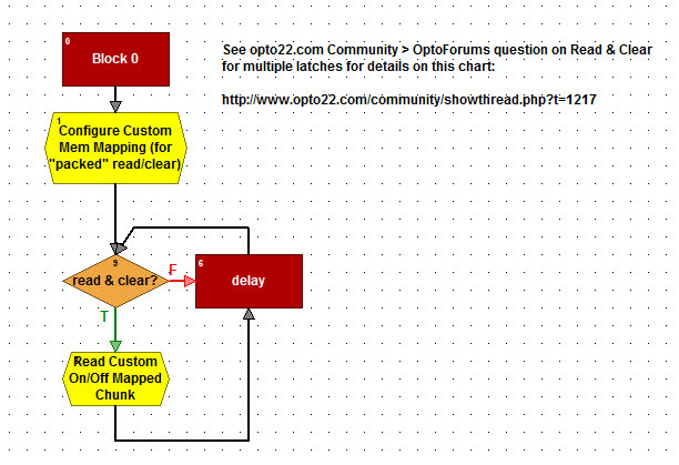
That first OptoScript block 1 loads up those read/clear on/off addresses (shown in the previous post) into that F0D5 0000 Config area for subsequent re-direct reading from that handy-dandy “Custom Data Access” area at: F0D6 0000.

So the set-up code looks like this:

nResult = 0;

nMemMapCustomConfigAddress = 0xF0D50000;// config area for custom mem mapping, start at the top for On-Latches, 
     //Off-Latches will be at: F0D50100

// Loop through all the points and map the read/clear addresses to the "custom" area for easier access later
nModuleIndex = 0; 

while ( ( nModuleIndex < 16 ) and (nResult == 0 ) )

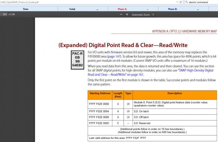
  // map the ON/OFF LATCH read/clear areas (see form 1465 on www.opto22.com for details) 
  nMemMapReadClearOnLatchAddress = 0xF02E0004 + (nModuleIndex * 0x600); 
  nMemMapReadClearOffLatchAddress = 0xF02E0008 + (nModuleIndex * 0x600); 

  nPointIndex = 0;
  while ( (nPointIndex < 4 ) and (nResult == 0 ) )

    // 4 points per module x 4 bytes per point x 16 modules = 256 or 0x100 (hex)
    // Configure the address to read, first the on latch, then the off latch at 0x100 off
    nResult = WriteNumToIoUnitMemMap( MyIOUnit, nMemMapCustomConfigAddress, nMemMapReadClearOnLatchAddress );
    nResult = WriteNumToIoUnitMemMap( MyIOUnit, (nMemMapCustomConfigAddress + 0x100), nMemMapReadClearOffLatchAddress );


    nMemMapCustomConfigAddress = nMemMapCustomConfigAddress + 4; // each address is 4 bytes

    // each latch address is 18 hex from the next one
    nMemMapReadClearOnLatchAddress = nMemMapReadClearOnLatchAddress + 0x18; 
    nMemMapReadClearOffLatchAddress = nMemMapReadClearOffLatchAddress + 0x18; 

    
    IncrementVariable( nPointIndex );

  wend
  IncrementVariable( nModuleIndex );
wend 


I hope that makes sense! Import the 9.3 basic (or better) chart attached below to save yourself some typing…

-OptoMary

GetClearIOUnitLatchesExampleB.zip (2.4 KB)

Mary, awsome reply. Unfortunately, I did not remember to answer your reply earlier this week. I am reading from [B]G4EB2’s[/B]. On the other hand would probably need the EB2 version anyway at some point. Also, by writing I meant “clearing” which I assume is a write. So I simply need to get and clear all latches from a brain. Now, correct me if I am wrong, but this also could be used in place of block reading all [B]input IO[/B] since you are clearing the latches each time you read, there is no need to read the IO point itself because the latch is cleared each time. The difference is if you only need to know if it is [B]still on[/B] or [B]still off[/B]. In most cases this doesn’t matter.
I gather from your reply that for exactly this type of operation the brains have an area that provide for custom configuration of what you want to read or write to the brain and when configured, the brain automatically goes out and assembles that data and put it into a sort of “Scratch Pad” memory area to be read by your application?
That’s pretty awsome…

“…would each element in that Rack1On_Table represent a bitmask for the module in that position? Or perhaps just have each element in that table represent one point? (For a max of 64, like the “Move I/O Unit to Numeric Table” command?)”

I had not thought that far ahead, but that’s a good point. I was assuming that the IO would be like the command work which is based on largest module. So 0 - 511 in the case of 32 point modules or in my case 0-31 elements in the table. Might require a different config for each “max” module size.

I know this is old but it’s something a lot of people can use.

I have created a memory map using the Custom Configuration Area - Write. Just as Mary above did so, here is another means of doing the same and in my case I am attempting to read all 16 4-point modules as well as all On-Latches in one read.
This is an OTG file that only has all the values pre-mapped so that you can take this and import it into an existing strategy and be able to read the areas that Mary refers to above. Read the
FFFF F0D6 0000 to FFFF F0D6 01FC and you should see the first 64 elements of the table as IO 1-64 and the second 64 elements as On-Latches 1-64.
Use the “ReadNumTableFromIoUnitMemMap” command instead of using “MoveIoUnitToNumTable” and get both points and latches.Points&Latches.zip (1.0 KB)