I am using the SNAP-AOV-25 to give a 0 - 5 VDC output to a thyristor for a heater control.
I have used a SNAP-AOV-5 previously to do this job but the current project needed to use only 1 rack because of space limitations.
The SNAP-AOV-5 is working fine with no problems at all, however the SNAP-AOV-25 is not working as I expected.
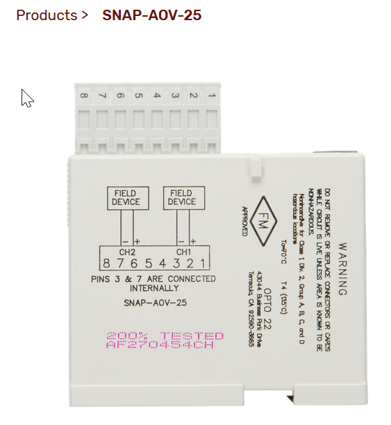
The 5 VDC supply to the AOV-25 is the same configuration as the AOV-5, in other words it is looped through the +ve terminal on the module (terminal 2) and out (terminal 3) to the thyristor and back to the -ve 5 VDC.
I would expect the AOV-25 to be able to adjust the voltage between 0 and 5 VDC as this is what is set up in the software via the ranges. Unfortunately there seems to be no control at all from the card
(0 - 5 VDC is equal to 0 - 100% output).
Testing the output of the card gives me 5 VDC continually and it gives that voltage on all of the terminals on the module.
Why is the 5 VDC output from the card not regulated in any way (0 - 100% output) and why does each terminal give 5 VDC.
Any help would be greatly appreciated.
Kindest regards
Paul