Groove RIO PID loop rocky start

I inherited a Groove RIO that is controlling an oven.
It is running PID loop that is using TPO (Time Proportional Output) to control the heating elements.
As you can imagine, it is a slow-moving process with a long reaction time. We use ramps to control the heating cycle so I typically start at ambient and slowly ramp the temperature up.
My problem is with the initial behavior of the PID loop. I typically start with a set point well below the oven temperature, so the oven should not heat up at all, but as soon as the process starts, output spikes for no reason. Unfortunately, with the large Kd, it takes a long time for a spike to dissipate so the oven is heating when it should not.
What am I missing here? It looks like the PID algorithm has some bogus initial values that lead to bogus output on the first cycle/scan that generates a bogus output.
Is there a way to calm the PID for the first few cycles and then let it do the job?
Btw, the oven is tuned really well, after the initial hiccup, I can track temperature +/- 0.5C without issues.

Hi Petr, welcome to the forums!

Can you shed a little light on what is controlling the RIO?
It sounds like its not standalone? Words like ‘as soon as the process starts’ tells me that something other than the RIO is starting the process and thus controlling the RIO?

I ask this because if you have a controller / software in the mix then we need to take a look at exactly how its controlling / managing the PID loop on the RIO.

In other words, I don’t think its the RIO PID loop per-say that is the issue, but how its been switched/controlled.

Reading this some more, you mention that you start ‘with a set point well below the oven temperature’.
If you are only switching the set point when you are ready to ‘go’, that could be the problem there.
Try having your control software set the PID set point to be the oven temperature as its warming up as per your ramp.
Since the PID sees the oven temperature is at the set point all the way along the ramp time, it will not drive the output and just go along with the ramp.
Once your ramp is where you want to be, the PID will take it from there with no jump.

If you are leaving the PID set point where the ramp started and only then setting the set point to where you want it to be, that large change is what’s driving the PID output so dramatically.

I haven’t used the PID feature on a RIO yet, but the Velocity algorithms don’t bump the output when the setpoint changes. If the RIO PIDs are the same as PACs and EPIC, then you shouldn’t need to retune any of the parameters.

1 Like

To clarify, imagine the oven having an ambient 25C and the ramp staring at 20C ramping all the way to 90C.
The expected behavior is to see no output till the ramp reaches around 25C and then slowly increase the output.
What I see is no matter what is the initial ramp temperature, PID kicks the output to a non-zero value on the first cycle, then it realizes it was a mistake and tries to backtrack and crawls to zero. It seems like PID bug to me.

No, there is only RIO.
I had to squeeze the most out of the RIO. I wrote the flow in Node-RED to drive the oven’s touchscreen and also the process that is calculating a setpoint based on a predefined multi-point ramp.
Basically, on every cycle, I calculate the setpoint based on the time from start in Node-Red, then I feed it to PID loop variables, and I take PID loop output and I feed it back to Node-RED to a simple TPO flow that feeds it back to the output.
It is a bit convoluted but it does the job.

Which algorithm are you using? When you “start the process” what is the state of the PID before you start and what gets changed on it to start it? Are you changing the setpoint while the Mode is in Automatic?

A screenshot of the PID configuration may help us understand as well.

I think Phillip is on the right track here. The behavior described seems similar to PID Auto/Manual switching without setting the SP to the current PV and tripping reset… especially with you long loop times. Seems like the PID is trying to drive - having no effect applying more and more gain and then suddenly it IS driving.

Using one of our RIO demo centers which has an ICTD temperature sensor with a resistor in the probe, I was able to run some PID tests to see if I could see what you are describing.

Starting first with straight analog in analog out control of the PID loop:

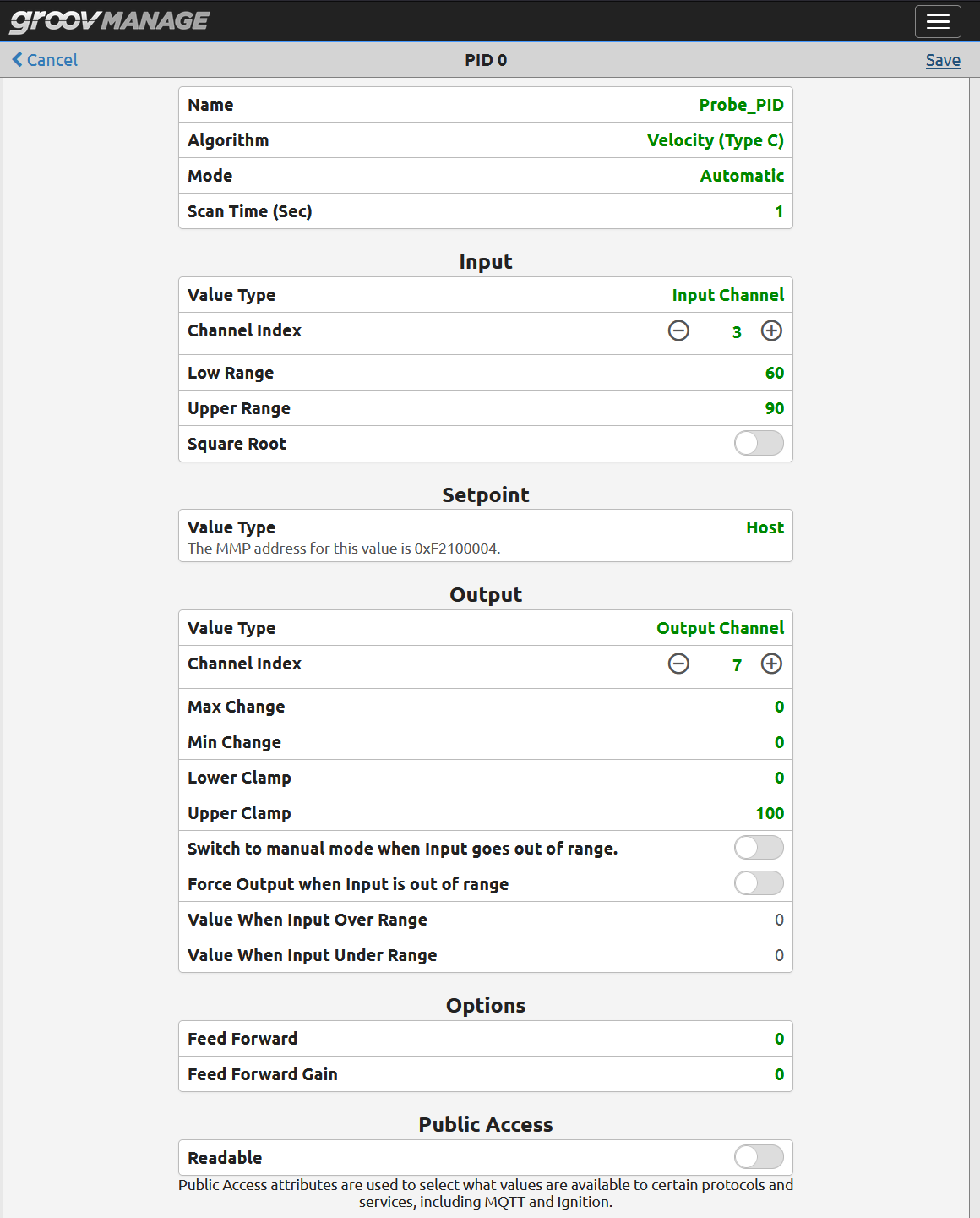
This is how its configured.

Now for the test:

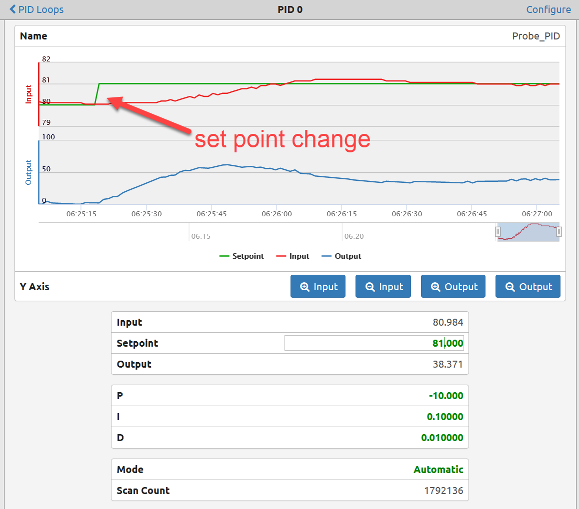
The PID responds smooth enough for the haphazard tuning values I threw in there to get started.
As expected, there are no jumps in the output when the set point is changed.

Seems to be working out of the box as expected, so lets now test the PID in TPO mode using Node-RED.
To do this, we need to use @torchard flow, you can grab it here (As no doubt you already have since you using the PID loop in TPO mode).

I changed the heater probe from analog to digital and here is the Node-RED graph of a set point change.

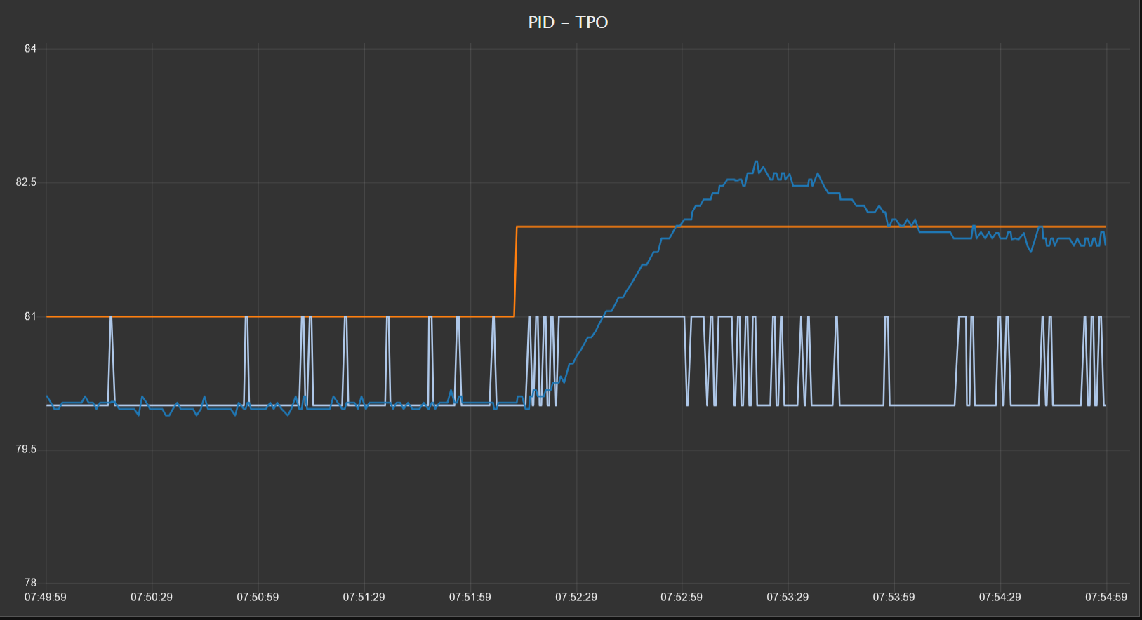
The orange plot is the set point. Made a step change in it and you can see the TPO (light blue plot) pick up the duty cycle smoothly, the temperature (blue trace) ie, oven temperature in your case, responds smoothly to the extra energy going to the heater element due to the TPO duty cycle.
The loop is poorly tuned, but none the less, the temp settles at the new set point and the TPO backs off just as it should.
There is no jump, no ‘initial hiccup’, no output spike, just smooth even control as expected.

If there is a PID bug, I cant reproduce it here.

Terry and I would be more than happy to review your Node-RED flow and get the TPO section dialed.
Just let us know how we can help.

2 Likes

You won’t see this behavior when using the Velocity algorithm as a setpoint changed doesn’t bump the output. You may want to test using ISA.

Velocity is the only algorithm I use now because it behaves so much better than the others (change the setpoint without upset and change the output while in auto - only downside is no proper feed forward support).

Velocity is the default. Without anything to go on from @Fogl I just assumed that the RIO he inherited would be using the default. Bad to assume I know, but I honestly suspect that its the TPO setup in Node-RED that is causing the bump rather than the actual PID type.
For example, as you know, setting the TPO period over and over is not a good idea… That’s just one place it can get a bit hiccuppy. (That’s a valid technical term right?)

I want to practice PID, is there a way to get those ICTD with heating resistor?

The original SNAP-PAC Learning Center came with them, also the EPIC Learning Center comes with them.
Outside of that, its dead easy to make your own, zip tie a resistor of the appropriate value (based on what signal you are going to use to simulate the heater - warning, of course it must be low voltage!) to a temperature sensor.
You don’t have to use an ICTD, it could be a thermistor or thermocouple etc.

I saw grv-mm1001-10 output voltage can only take 7.5k Ohm.
So I found 10k Ohm, 1/8 watts.
Attach this resistor to the ICTD.
Is this it?
How Opto guys did it?

Thank you Beno.

Doesn’t seem like you will get a lot of heat out of a 10kohm resister at 10v (10mW).

The learning center resister measure out to be 330 ohms. The RIO short circuit current is 20mA. I would go with a 500 ohm resister and use the 0-10V output or 4-20mA output for your signal.

I don’t know what the 7.5kohm minimum load resistance spec is about. If you’re concerned about that, then use the 4-20mA and you are good with 500 ohms.

Right Philip, Thank you.

Then which output is this 330 ohm from learning center connected.

I plan to use analog voltage output of grv-mm1001-10.
There will be no other IO connected aside from the ICTD probe and the resistor.
I don’t mind trying 330 ohms (30mA) or 500 ohms (20mA), as long as someone can tell me, i won’t bust the mm1001 drawing this amount of current.

The mm1001-10 is current limited to 20mA, so you are better off using the 500 ohm to get the most out of it. The 330 ohm will be current limited at 6.6V so you won’t get the full scale or maximize the “heat” output with it.
Since the mm1001-10 is configurable, you could also configure your output as 0-20mA as well, it will effectively do the same thing as 0-10V when using a 500 ohm resister.

1 Like