The Modbus “standard” can be a somewhat non-standard sometimes (you’ll see various: interpretations of the standard, options and their names, word-order/Endianness, etc). Also, not all Modbus device manuals are as detailed or helpful as one might like.
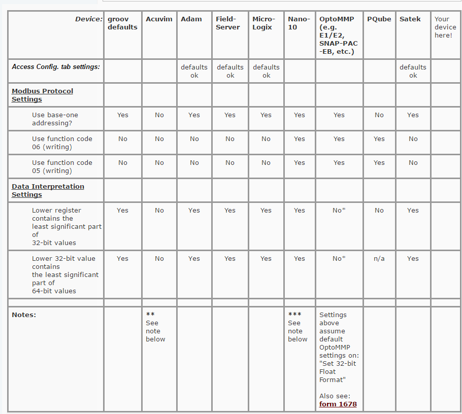
So… to help you connect any Modbus devices you’d like to monitor/control with groov, we’ve compiled a list of popular Modbus devices and their corresponding settings in groov…
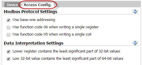
especially what we call the Access Config. settings (defaults pictured here):
On that previous post, be sure to scroll to your right to see more Modbus devices (listed alphabetically). Also be sure to let us know if you have one you’d like to add to this list, or find these settings did not work for you.
** Note on Acuvim:
Watch how addresses shown in their manual, like: 4000H since that H means Hexadecimal – you must convert to decimal for groov, e.g. 16384 (vs. 0x4000).
*** Note on Nano-10 PLC:
Watch extra digits on address - since groov pre-pends the 4 (for Holding Register). You’ll need to drop the pre-pended 4 for your tag settings.
Sample tag config for DM[] values:
[B]More details on these groov Modbus settings in general:
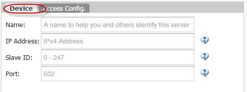
[/B]The Device tab:
[B]Name: [/B]meaningful to you: like the brand and/or location of your Modbus slave device)
[B]IP Address: [/B]or URL/hostname
[B]Slave ID: [/B]aka “Unit ID” -- often 1
[B]Port: [/B]aka “Service Port” -- usually 502
More on the Access Config. tab settings show in the table above - defaults shown: [x] vs [ ]
[LIST=|INDENT=2]
[U]Modbus Protocol Settings[/U]
[x] Use base-one addressing
[LIST]
If this setting doesn’t match your Slave Device, your Tag Addresses will be off by one. Check your Slave Device manuals to see if they start at 0 or 1. Sometimes the 0-based numbers are called “Register Address” (vs. “Register Number” for 1-based). Modscan, the popular troubleshooting tool from WinTECH software, always does 1-based like the groov default.
[B]NOTE: If this setting doesn’t match your slave device, you could still end up with okay-looking values if you also have a mismatch on your “Data Interpretation Settings” below.[/B]
[ ] Use function code 06 when writing a single register
[ ] Use function code 05 when writing a single coil
If these function code settings doesn’t match your Slave Device, you may get errors on writes.
Not all manuals will mention which Modbus function codes are supported by the device.
ModScan has a different default than groov -- it will use the single-point write functions: 05 and 06 rather than the alternative: 15 and 16 (write [I]multiple [/I]coil and register)
[/LIST]
[/LIST]
[LIST=|INDENT=2]
[U]Data Interpretation Settings[/U]
[x] Lower register contains the least significant part of 32-bit values
[x] Low 32-bit value contains the least significant part of 64-bit valu
[LIST]
See bold NOTE above re: base-one. These "data interpretation" settings relate to word-order aka "Endianness" so if you're seeing weird values on your reads, try toggling both of these. If that doesn't help, try addresses one less or one greater than those you're currently using for your tag settings.
[/LIST]
[/LIST]
Also don't forget that our [[U][B]product support[/B][/U]](http://www.opto22.com/site/support.aspx) is FREE! (we recommend contacting them via email) and they've been supporting Modbus devices for decades.
How do I keep my pac controller from fighting with my groov box over a Modbus VFD setting (speed input). I am currently using a modified version of the Modbus tool kit on the controller and just tried to connect the groov. I can get it to connect, but the controller input overwrites the groov input. How can I get both to work together? I don’t really want to strip it out of my control strategy (I need it for PAC display).
Also, No ABB Modbus in your Access config? That makes me sad…
There might be a few ways to do this (OptoMary will probably have 10 different ways…), but its a classic issue that many of us face… Having a UI (User Interface) and a program (Strategy) controlling the same output.
At the class here at Opto, I always strongly suggest that people design the UI FIRST and then write the strategy.
Sounds like you have had the strategy running for a bit and then added the groov UI.
So, in this case, I would attach groov to a variable in the strategy, have a little code that decides if groov (the user) or the strategy should write to the VFD.
You, and only you, can decide what the deciding code would look like.
Bottom line, the drive can not read the users mind and chose which of the two devices writing to it should win.
You, the programmer, need to decide for it.
I’m not exactly sure what you mean. Were you looking for an ABB column in the matrix above? While we haven’t tried EVERY Allen Bradley device known to man, check out the “Micro-Logix” column. While the Modbus protocol in general is notoriously non-standard, let’s hope A-B was at least someone standard in their implementation across their own products…
If that wasn’t what you were looking for, please elaborate. We’re currently working on some other groov/Modbus improvements now, so your timing could be good!
Also, if you’ve used groov with some other devices that I have NOT listed in this matrix, I hope you’ll share the settings that worked for you!
Ah! Please forgive, and thank you for the clarification. Did you have a particular product in mind? I’ll see if we have any around here.
Did or could you try the free-trial with something ABB? Or perhaps you have something you could share/expose over the Internet that I could try to figure out what these settings should be for you?
FYI - those “access config” settings were designed to work with any/all Modbus TCP devices, and I’ve tried to list the correct settings for as many Modbus TCP devices I can get my hands on, but alas, there are so many hours and dollars in a day…
To be honest, Modbus TCP is a little out of my league. I can get something to work with enough poking/prodding + the usually obtuse manual using Modbus Poll to figure out addressing, but to say I know what I am doing would be a stretch.