Hello,
I’m having questions with some wiring connections to the Groov RIO 26-pin terminal block. I checked the specs and confirmed the terminals accept wire sizes from 28-14 AWG. We are using an 18 AWG wire, but with a ferrule. This makes it very snug when inserting the ferrule to the terminal once the clamp is opened with the provided tool (or thin screwdriver). And once inserted, sometime it is very difficult to remove the wire with the tool, unless a lot of wiggling and turning is done (maybe damaging the connector?).
I wanted to understand what Opto22 recommendations are (or maybe others have found a good solution), as the ferrule on the 18 AWG stranded wire causes the wire size to increase to an equivalent of 13 AWG (1.8 mm). The max spec size (14 AWG) is equivalent to a wire size of only 1.6 mm, so I can understand why we might be having these issues with the connection being very snug.
With an 18 AWG stranded wire, should we just twist the wire and clamp it on in the connector and not use a Ferrule?
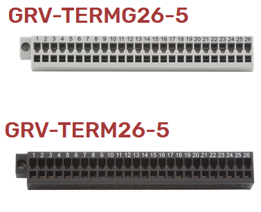
Another question, which is somewhat related to the above and what triggered this investigation: Is there dimensional or spring clamp differences between the Black and Grey Opto22 connectors, other than the grey is rated for thermocouple channels (gold plated?). We have a customer with a Groov RIO but using a black terminal block (GRV-TERM26-5) (by default, I believe RIOs come with the Grey terminal block GRV-TERMG26-5)… and they are experiencing intermittent sensor connection issues. After they establish a “good” connection, simply wiggling the connector to the RIO lightly can cause the disconnect in one of the 4-20 mA inputs, causing PID-loop issues (Temp values goes to zero). I wanted to rule out if the Black/Grey terminal block could be the culprit, or if it is due to the ferrule size potentially widening the wire clamps too much and/or damaging the spring clamps during install.
I’m hoping someone can enlighten me as I would expect this can’t be the first time someone has ran into a similar issue. Attached is a pic of both Groov connectors: