Next item sitting here is a 24v dc solenoid valve that has 3 wires. No wiring diagram online that I can find, but a few videos that basically say the 2 red wires have no polarity.
Which output to select on the Rio and how to hook up this solenoid valve? I believe it’s Voltage Output and (assuming channel 4), connect the 2 red wires to 13 & 14…but where does the ground go?).
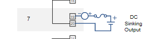
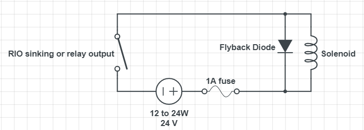
You would use one of the relay outputs or DC sinking outputs along with a 24VDC power supply in series (1A current limiting or include an inline fuse). Since this is a solenoid (inductive), you will need a diode across the solenoid in the reverse direction to suppress transients when the coil is de-energized.
Here is a drawing with the diode drawn in. A 1N4001 diode should work fine along with many others.
In short, listen to @philip
That said, have a part number for the solenoid?
The fact that its three wire has me intrigued.
But yeah, I would wire it one wire to positive, one wire to the RIO output and the third wire to the RIO output ground.
The third wire is a grounding wire that should be connected to the equipment grounding conductor. Not to be confused with Beno’s use of the word ground. The two reds are what you would use in the above circuit.
Uh, rushing while having dinner… my bad, I totally missed the link to the device…
Yeah, its not an active device at all (as I was thinking it might have been).
Like I said, listen to @philip
Thanks guys. I will pick up a 1A fuse and flyback diode to do this right.
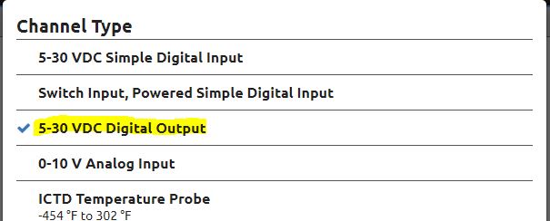
Just to clarify, my options on the Rio to use this solenoid is EITHER one of the relay outputs OR a DC sinking output (along with a 24VDC power supply). I can see the Form C Relay option in channel 8 & 9, but where is the DC sinking output choice (in the other channels). This one?
Im currently at home and don’t have a RIO here… I know, I know…
But, here are my notes on the digial output from a soon coming video on the RIO I/O.
Discrete DC Sinking output is when the RIO acts like an SSR, a solid state relay. It will turn on and off an externally supplied 5 to 30 volt DC source. The key to note in the specifications on this point type is the maximum continuous current of 1 amp. You should make sure you have external fusing or current limiting to ensure this is never exceeded. Also note that just like an SSR, there is a tiny amount of off-state leakage current.
Got it. I probably will use the Form C relay since I have no other planned use for channels 8 or 9.
And finally, last in my box of unused electrical gadgets, I have this inductive proximity switch. Originally, I thought it would behave the same way as the reed (float) switch, but hooking it up in that way has not yielded any change in the state (I am expecting a state change when I pass something info front of the prox switch). Any thoughts on how to get this working with the Rio?
Yep, don’t know much about those - looks like it is designed to be in series with a DC load of 6-36VDC and allows current to flow when near an object, and just leaks a bit when open.
Spec sheet on that is hard to find, but it looks like it uses around 8mA (so the switch inputs on the RIO don’t provide enough excitation current). If you have a spare RIO analog output channel, you could set it up for 0-10VDC output and use that as a “power supply” (set to 10VDC output) for the proximity switch wired in series with a DC Input channel and see if it works.
Edit: DC Input channel won’t provide enough load to pass the current needed. You would need to try using a analog current input which should swallow the whole 20mA the 10V DC analog output can muster. If that works, you will read something like 8mA when the circuit is open and 20mA when the circuit is closed. If that works, then you can source yet another DC power supply (and fuse) for a proper power source.
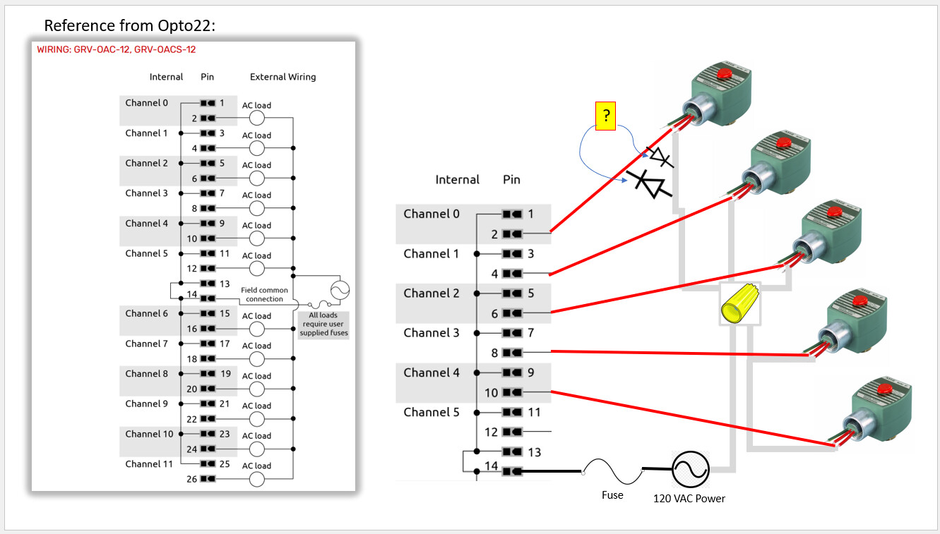
This is about 2 years over my originally planned timeline, but I finally got one 120 VAC Asco solenoid valve working with the GRV-OACS-12 module on our EPIC. Now I would like to control five (5) solenoid valves using one GRV-OACS-12. Below is how I did the mockup (I am not any electrician, and it shows). On the sketch, I inserted the flyback diode between the two red wires of solenoid #1 (but once I determine the course of action, diodes would be put in place for the other 4 solenoid valves). My question is two-fold…Do I have the flyback diode correctly placed, and if yes, which of the two directions shown is correct? Does everything else seem OK? One fuse for all 5 solenoids?
A few things here.
First up, you don’t need (and should not use one) a diode for AC solenoids. A diode will try and rectify the AC wave to a half wave. Bad idea.
Secondly, the spec sheet mentions that the module features:
groov 12–250 VAC output modules are used to switch up to 12 separate AC loads. They provide 300 volts of transient protection between field signals and the logic side of the modules. AC outputs are zero voltage turn on and zero current turn off to minimize transients during switching.
This means that they will turn on when the AC voltage is passing through zero volts your solenoid will get a ‘soft turn on’ as the voltage ramps up.
On a turn off command, the module will only switch off when it sees the AC current flowing to the solenoid is at zero. If the current is zero when it turns off then there is no back lash so no RC (resistor capacitor) snubber circuit is needed.
Bottom line is to remove the diode and don’t worry about putting in a snubber circuit.
The one thing you DO need to worry about that you did not mention is the VA or wattage of each solenoid valve.
The current rating of the module is 0.5 amps per channel. That’s straight resistive, but the solenoid might be more inductive so its spec sheet should be consulted to see what its max rating is.
All of this then brings is to your last question about fusing…
The answer is partly a personal choice one.
Can your process keep running with 5 down’ed solenoid or would it be better to just lose the one that goes shorted?
ie, when one goes bad, do you want to lose all of them or just that one?
If you just want one to go out, then fuse all 5 with a lower rating (usually about double the VA of the valve) fuse.
I did set up a 24VDC solenoid a few weeks ago with the ODCIS-12 which worked perfectly. When/if I do get that one running, what is the direction of the diode (just to avoid asking this 3 months from now)?
So, takeaways / feedback from the above are:
no flyback diode on the setup with the 120VAC solenoids
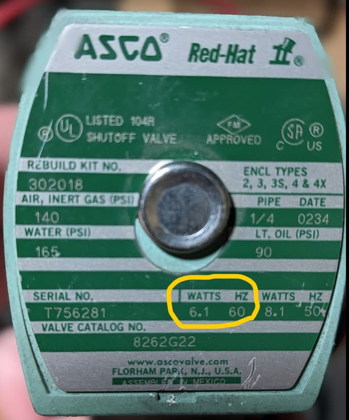
the solenoids in question are rated at 6.1 watts. Is this OK for use with the GRV-OACS-12?
a single fuse is fine so long as we understand that all solenoids will stop working when said fuse blows. Our process can indeed keep running. This whole setup is not production related…it’s to control sampling of gasses that is currently entirely manual (guy walks from one unit to another, opens valve manually, collects readings for 10 minutes, closes valve, moves to the next one, etc.). Soon to be replaced by the groov EPIC!
Thanks as usual to both of you. This particular application is a huge step forward.
Sounds like 1 fuse is going to be Ok for your setup as well.
For the DC, as Philip said, stripe on diode to the positive.
Also try and get the diode mounted close to the solenoid end vs close to the groov end.
You want to shunt the back voltage as close to the source as possible.