Good day to all! I am trying to control the direction of a mini servo motor for a robot arm project. I saw some posts here in the forums that the TPO is one way of Opto22’s PWM generation. I am using a Digital Output module (SNAP-ODC5SRC) to control the signal line of the servo motor. After I set up the TPO period and TPO percent I noticed that when I debug the flowchart and run the strategy the servo motor arm does not move. My knowledge on PAC Control is quite still limited so any form of ideas/knowledge is quite appreciated :D.
Questions is:
How do I control the direction of a servo motor arm? Is it possible through the digital output module? or Do I need another hardware for this?
I am planning to control 6 servo motors (robot arm) using my Opto22 Learning Center. Is it possible for multiple digital outputs connected to my learning center to run multiple TPO outputs simultaneously?
Interesting project and great timing. @torchard and I happen to be working on a project involving a few RC servos at the moment.
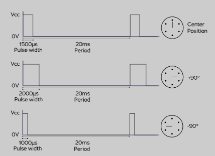
Im sure you have read up about how they work, They use a variable pulse width at the start, 20msec latter, they send the same pulse width or the new width based on the angle you require.
Here is the diagram from Wikipedia:
You can see how the width of the first pulse and then the next 20msec latter determine the angle.
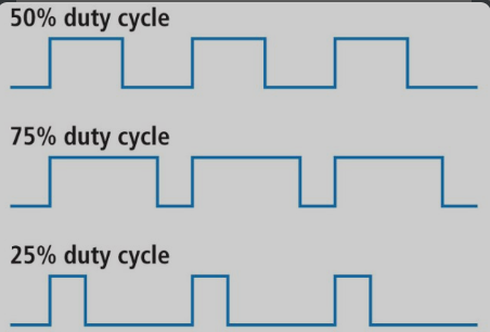
TPO on the other hand just sets the duty cycle of the pulse.
As you can see, they are totally different pulse trains.
Even if you could find a digital output module that could switch fast enough, it would be very tough to get the PAC Control code to make the RC servo pulses with the precision that the RC servo requires.
Bottom line, its not possible to drive an RC servo with either SNAP or groov hardware at this time.
So, what are Terry and I up to then?
We use another controller to drive the servos we need.
This is the one we chose. We need to drive 24 servos for our project.
This controller has many interface options. In your case, you might even find the small hand controller helpful in driving your arm manually.
The interface we use here is the serial interface. Note you will need a level converter to convert the ±12v from the SNAP serial port on the top of the SNAP controller to the ±3.3 that this controller requires.
We now have a chart or a bit of Node-RED (in the case of a groov controller) that sends the serial commands to the controller which then drives the servos.
There is no jitter or noise and it is easy to control that many servos at once via serial strings.
Hope that helps and gets your robot arm moving smoothy.
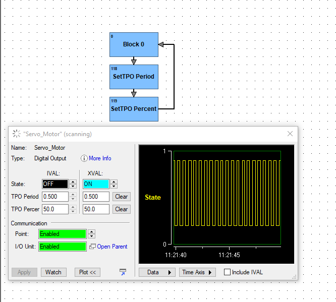
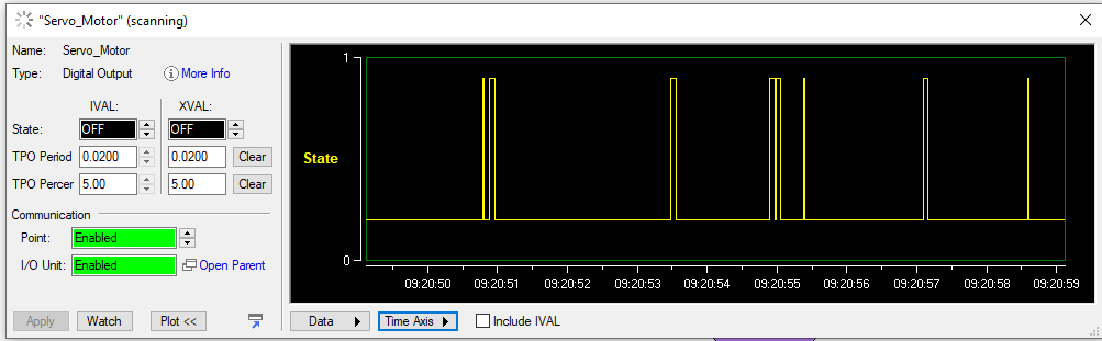
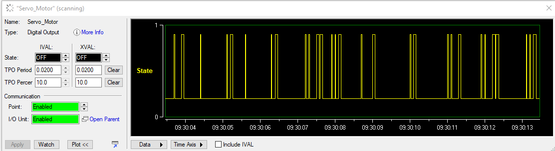
Hmm, I’m not seeing the difference. Brain and module capabilities notwithstanding, wouldn’t setting the TPO period to 0.02 and the TPO percent between 5% (1.0ms) and 10% (2.0ms) duty cycle give you the same pulse train as the servo example?
Based on your screenshot, you are sending the servo a 250ms on pulse which it won’t know what to do with. For the sake of experimentation and curiosity, and since you have it all wired up, can you change your TPO Period to 0.02 and keep the percent between 5 and 10 and see if you get movement?
As Ben said though, you will likely need some other hardware to have acceptable position control as the Opto equipment turn off and on time variability will likely cause the servo to jump all over the place.