I’m working on project based on an OPTO 22 snap-up1-ads, this project is already built and configured, I just have to make it work again.
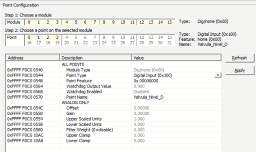
The problem is that one of the modules I have conected to the Opto was giving no signal, it is an analog output module (4-20 mA) but on PACManager it is configured as a Digital Input Module. I add a picture of the configuration info.
Is there a way I can change this configuration manually?
The UP1-ADS is an old legacy product. This application might use a ioControl program running on the UP1-ADS controller. Do you have the program file?
There are several reasons why a module is not recognized correct in PAC Manager. One could be, that the voltage on the rack is to low. It should be in the range 5.10 to 5.20 VDC. How to measure this is described in this manual.
A bit more information about the system would be good.
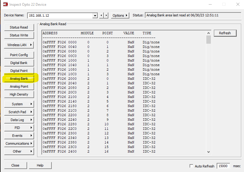
Based on your screenshot you are reading Module position 5, which is the 6th module counting from the side of the rack where the UP1-ADS controller is. The positions start from 0, perhaps you are reading the wrong module. Can you doublecheck this.
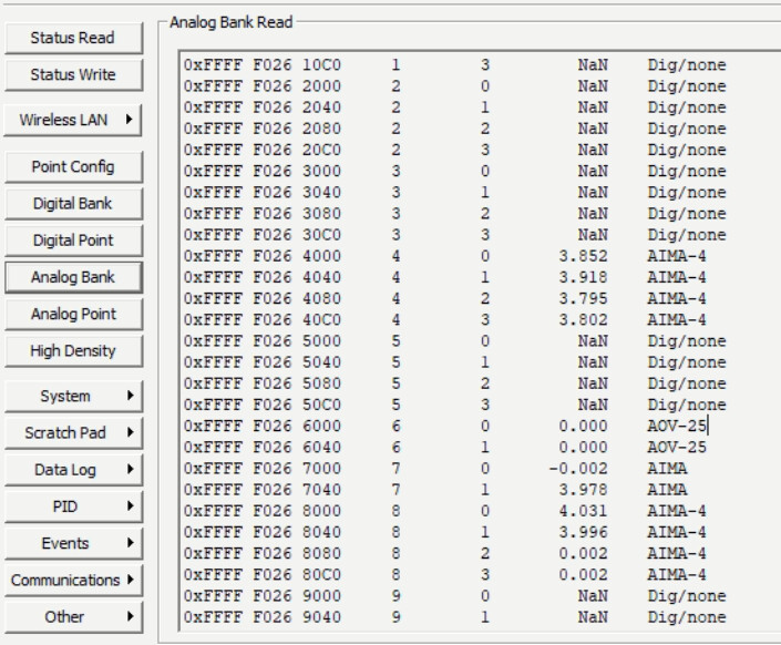
In PAC Manager, there is an option to do a Analog Bank read. That usually shows you all the analog modules that it can detect. Can you try that.
If you can, swap the position of the module with another analog one and make sure it also moves the NaN and that the different analog module in position 5 is now reading Ok.