I am trying to configure a R1 brain with the modules so that I can communicate with it via modbus correctly.
I am using PAC Manger, and I have the IO configured, but I can’t seem to figure out how to upload it to the brain. When i try to “send” it, the button is greyed out.
If i read first, then try to send it’s doesn’t seem to send what I have configured in Pac Manager.
Any reason to not use PAC Control to configure the I/O modules?
I think you will find it a lot smoother and quicker to setup all the I/O using PAC Control. The basic version is free.
You don’t need to add any charts, just setup the I/O, put in the IP address, download and your done.
No problem.
I mean, you can do it the PAC Manager way, but PAC Control will be far smoother and faster.
You can take a quick review here: https://training.opto22.com/creating-and-configuring-a-strategy
You don’t actually have to do the lesson, just use it as quick start guide.
The PAC Control manual will be installed on your computer, or you can find it here. Opto22 - 1700 PAC Control User's Guide
Page 117 is the same as the training, it walks you through working with IO.
So pick either if you want a bit of a guide.
Or just download it, install it and click around, I think you will find the I/O in the strategy tree pretty quick and add your modules from there.
You will need to look up the Memory Map address for the input you desire to read. You can search for document 1465 - OptoMMP Protocol Guide to get the memory map layout.
Analog Channel Read base address is 0xF0260000 with each module(slot) on 0x1000 boundaries and each channel on 0x40 boundaries.
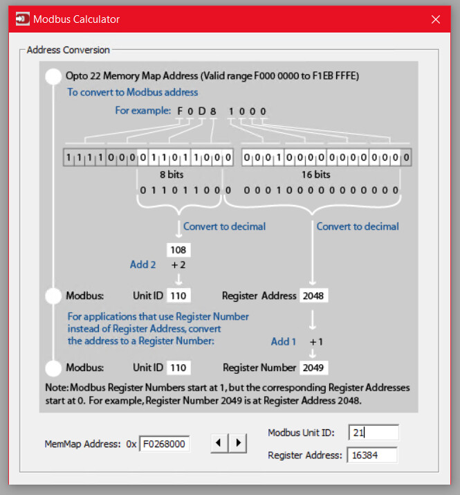
For Slot 8 channel 0 analog point: 0xF0260000 + (8 * 0x1000) + (0 * 0x40) = 0xF0268000
There is a formula to convert this to a Modbus Unit Id and Address, but it is easiest to use the built in calculator in PAC Manager (Under the Tools menu):
So the Unit Id is 21 and address is 16384 (+1 for register number- which is what Ignition will want if using the default values on the gateway when the Modbus device was configured, Zero-based addressing unchecked).
So the OPC path in Ignition would be [GatewayDeviceName]21.HRF16385
HRF since these are IEEE754 floating point values.
I didn’t test any of the above, so let us know if that works for you.
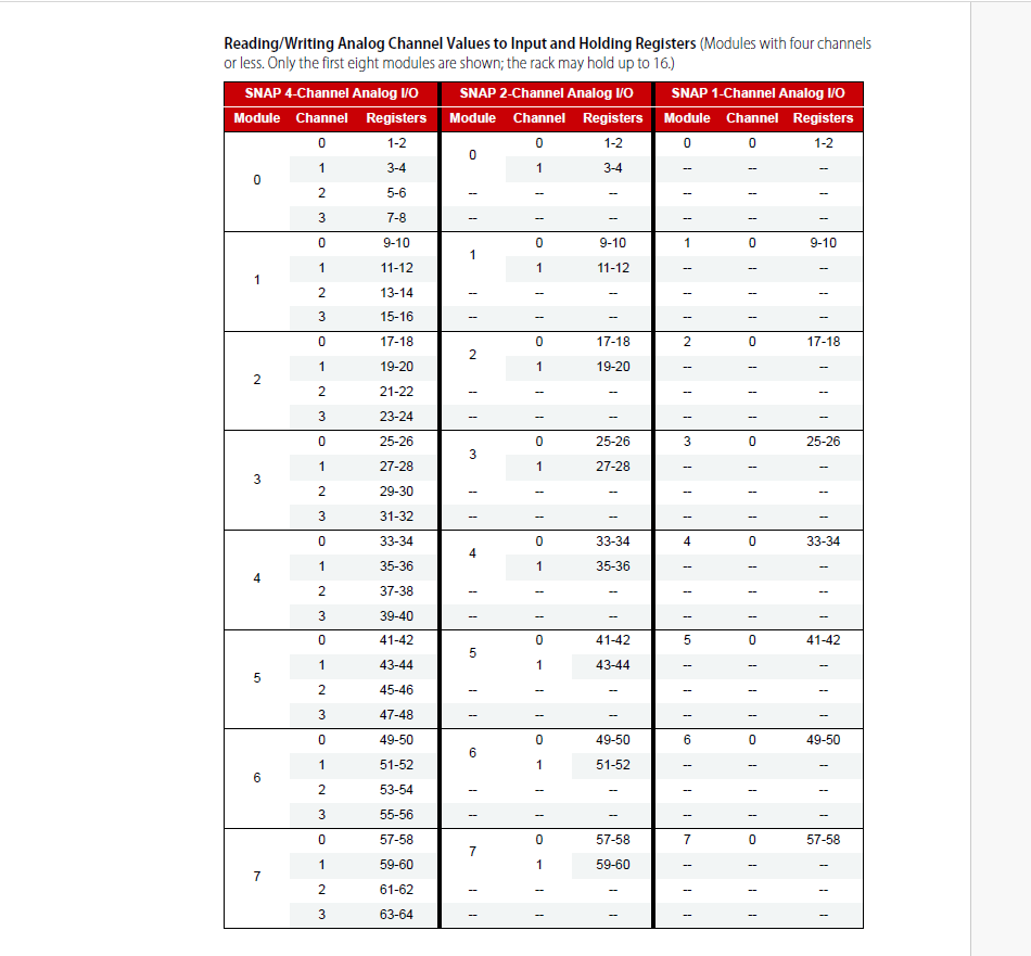
I don’t believe that works (at least doesn’t appear to be) and doesn’t seem to jive with the rest of the modbus documentation for SNAP-PAC as seen from below
The main reason I say that, is the coil inputs/outputs are all id 1, so I don’t get why an analog would be a different ID, and so far off from the table I posted
The Modbus area on SNAP, EPIC and RIO are so large we cant fit everything into one device ID, so have to use different device ID’s for different areas.
I haven’t looked at the 1678 Modbus guide - that has an alternative map that doesn’t cover the entire memory map, but will likely work as well.
For an analog input at module 8, channel 0, I come up with [GatewayDeviceName]1.IRF65 or based on page 42, [GatewayDeviceName]1.IRF5633 for new development which supports high density modules.