I will do this in Node-RED and plan to just use a function node to convert the pulses to cubic feet (100 cubic foot/pulse acc. to the utility guy). Is there more complexity that I am not seeing?
I will do this in Node-RED and plan to just use a function node to convert the pulses to cubic feet (100 cubic foot/pulse acc. to the utility guy). Is there more complexity that I am not seeing?
I was thinking of demand management. If all you are after is volume, then no, straight one-line Javascript math.
Too easy.
Yep, this is going to be a glorified flow meter that is one step up from my MacGyver camera contraption.
Hi @grant1 ! Sorry I didn’t see these replies until now.
How did your implementation work out?
We are using Ignition as the endpoint for the pulse meter data, and I haven’t gotten around to making the report yet.
Hi @luke.rector
The utility company delivered the pulse meter last week and we have not yet had a chance to hook it up. Should get it done in the next week or two and will post back here…
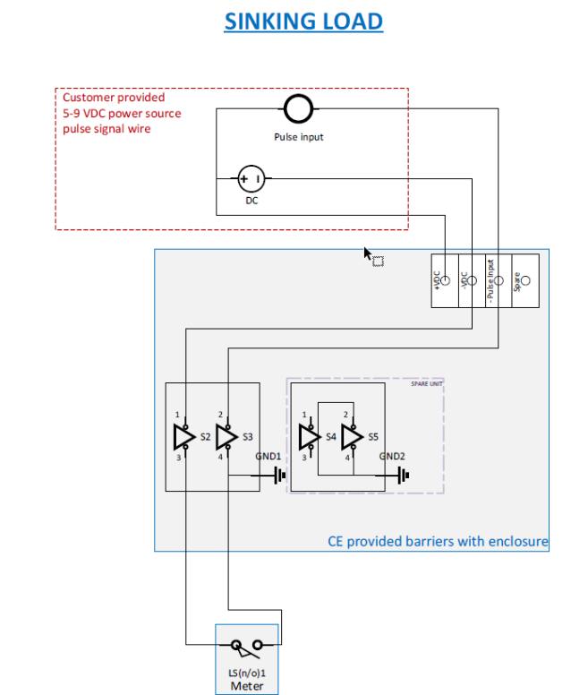
The gas meter co. is coming out today. This is the diagram they provided.
Is it safe to assume that the red box shown above is the Rio? If yes, then where does the wiring form pins 1 and 2 connect to?
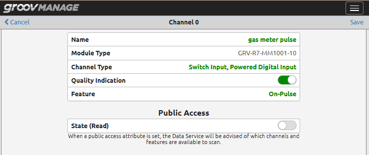
Any special settings here?
this is the safety barrier:
Uh, that barrier device makes things a lot more complicated than it needs to be, but I see the gas company side of things… they don’t know what each customer is going to hook up and the barrier protects the gas company from having to answer questions…
Thanks for attaching the barrier spec sheet… 8.6 volts max, but they don’t say what the min input voltage is, just the ‘nominal’ voltage of 6vDC.
I’d suggest a 6vDC supply (I’d be testing 5V, but that’s just me) that is floating (its ground is not connected to any other ground - most small plug packs do this - if you use something like a 5vDC Meanwell cranked up, you will need to check).
Put the 5-6vDC on the two power terminals of the barrier as shown on the diagram in the post.
The RIO is going to be interesting. You won’t be able to use the ‘switch input’ since the barrier is not a dry contact. You will need to use the ‘5-30 Simple DC input’.
The barrier pulls the +6v to ground via the - Pulse Input pin, but the RIO is looking for the opposite.
Since the 6v is floating, I’d be inclined to put the +6DC on the RIO pin 2 and the barrier pulse into pin1.
@philip for a sanity check on that idea
I’ll leave the software to you and whether or not you configure the first point to be a counter or not.
Thanks @Beno
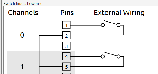
Turns out the diagram they sent us in advance was really not accurate. When the installer came, he simply wanted a 5 to 8 VDC signal. He hooked up his little counter which sent 5V constantly and counted every ~45 sec. when there was a pulse.
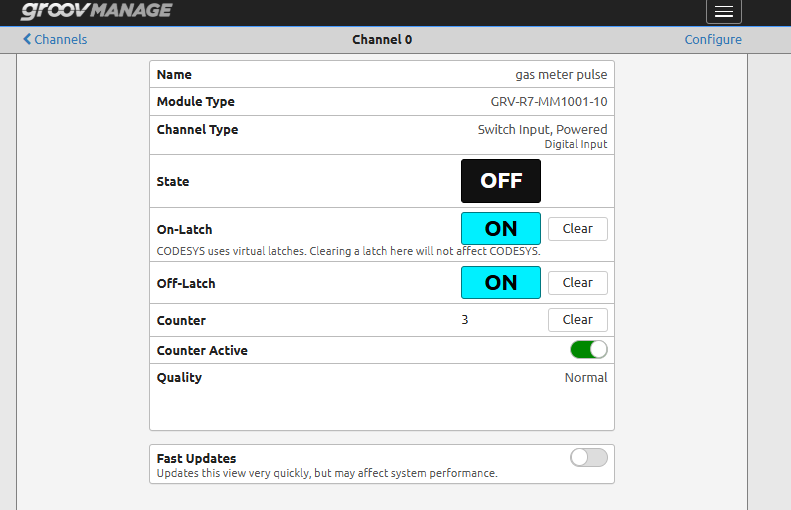
We rolled the dice and used the Switch Input, Powered Digital Input of the Rio and voila! it works:
Great follow up!
PNP vs NPN is a never ending issue for this sort of thing…
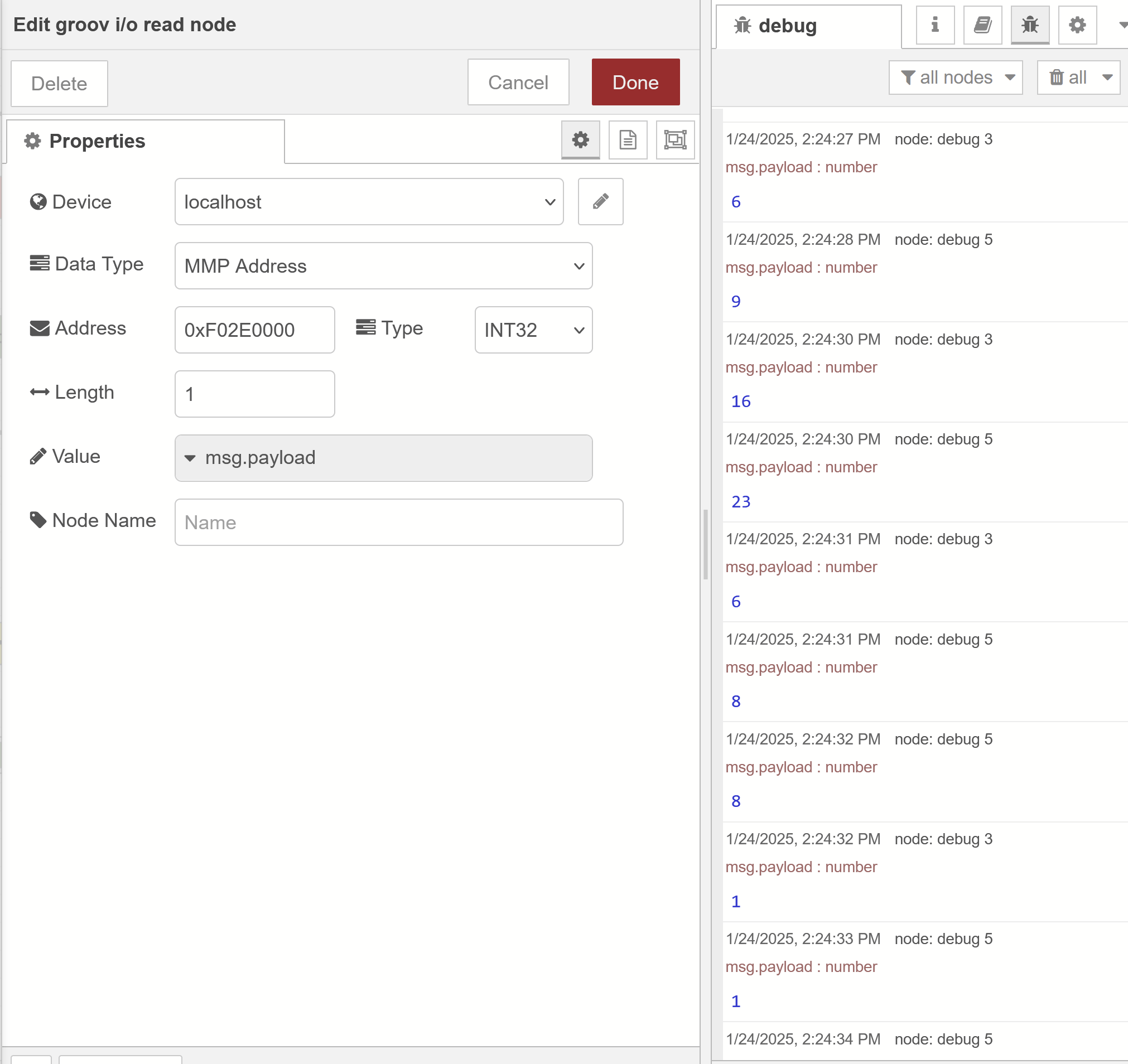
Moving on to Node-RED, what is the best way to view whenever a pulse comes through? I tried most of these and am not getting anywhere.
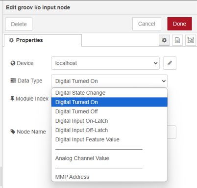
I presume Module Index 0 and Channel 0 are the ones to use
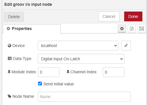
Nevermind: I think we got it. Just math from here on out…
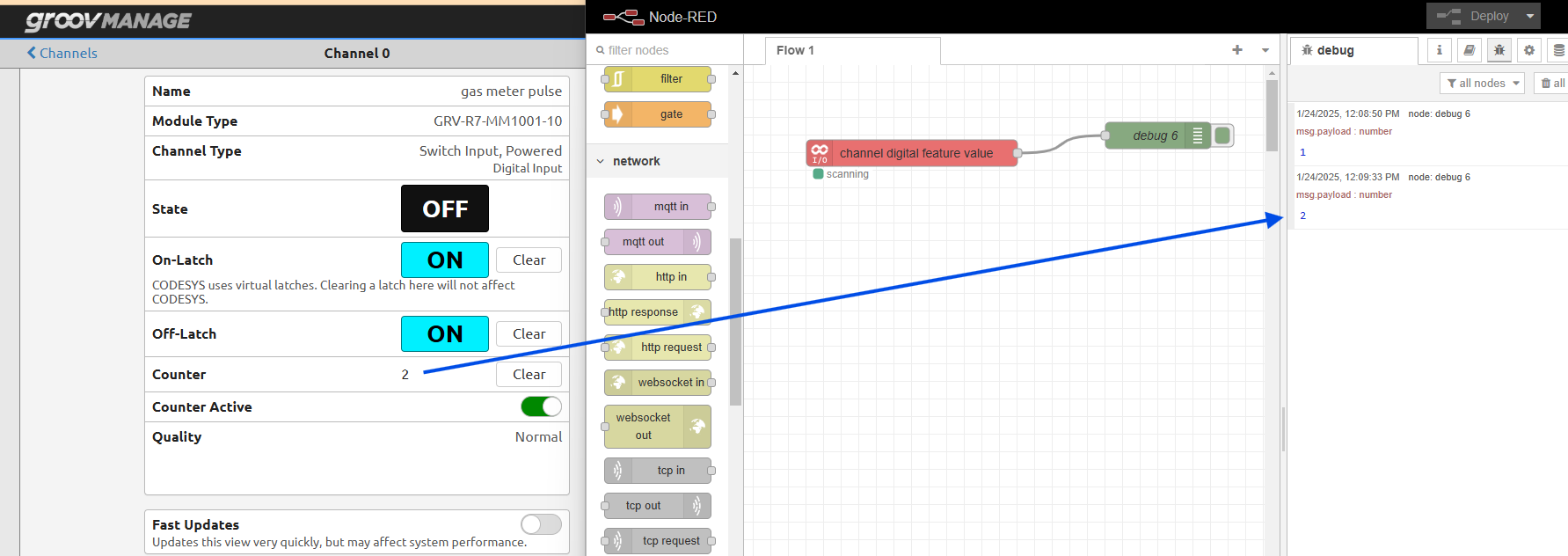
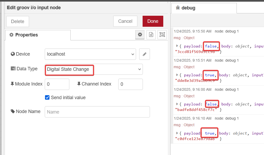
This is what I have tested just now on our power meter pulses…
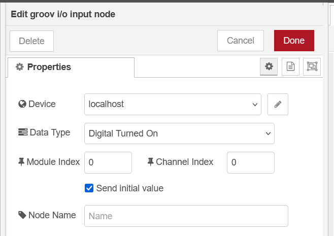
I get a ‘true’ msg.payload each time the pulse turns on.
Do you need to scan faster than once a second?
If you want to see each on off: