I am a new user to PAC Control and am still learning.
My task is to communicate two GRV-CSERI-4 modules using RS-485 using transmit string and receive string commands. This is a “Hello World” of sorts.
After following every direction outlined in the documentation PAC Control User’s Guide and PAC Control Command Reference I am still getting the error -39 for the Receiver Module. Here is a quick outline of the steps in my strategy:
Set the 2 GRV-CSERI-4 modules in slots 0 and 1.
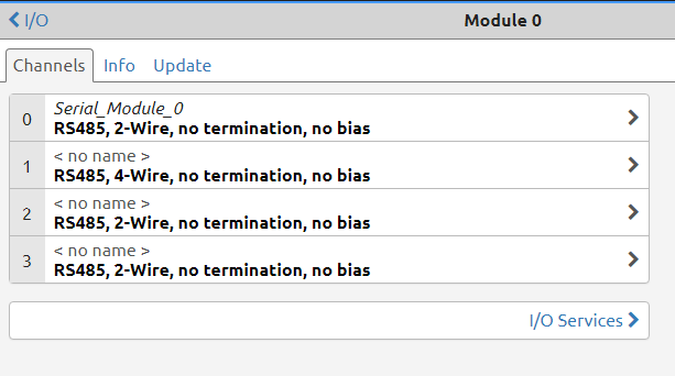
Configure the two I/O modules in groov Manage to RS-485, 2 wire, no termination, no bias.
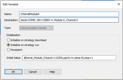
Initialized the communication handles to the following
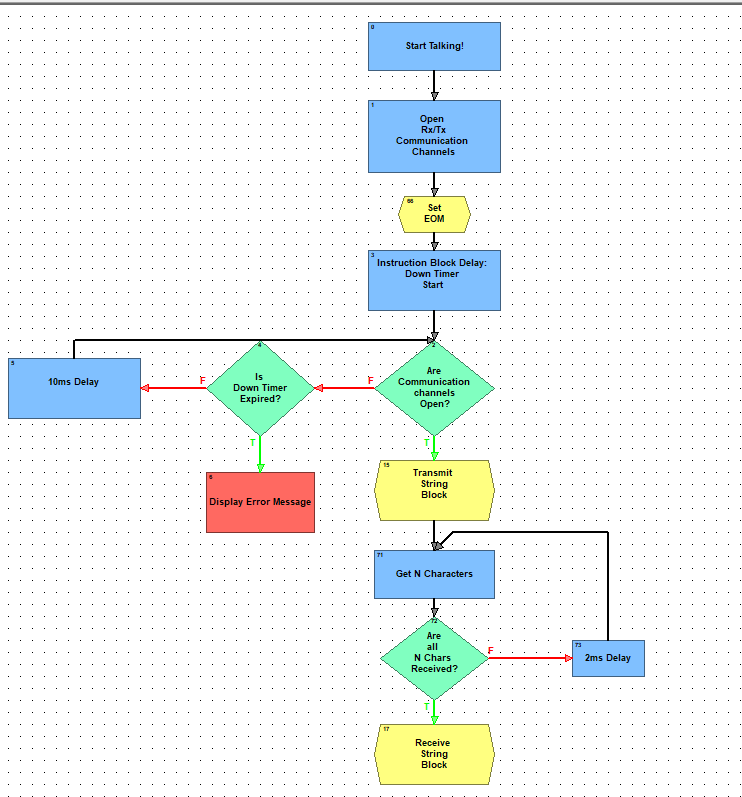
Opened outgoing communication with a downtimer to allow completion of operation of instruction after instruction is called.
Set the EOM for both Transmit String and Receive String.
Transmit
Receive
I have tried the following:
Using the recommendation as seen per the documentation such as Get Number of Characters Waiting
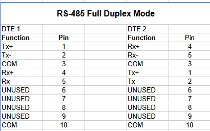
Ensuring I wired the modules correctly, see the pin map below
Ensuring that jumper wires from GRV-CSERI-4 Module 1 and GRV-CSERI-4 Module 2 are making electrical connection (using continuity test on multi-meter).
See below for my Strategy block diagram and .zip file
It kind of sounds like you want to transmit from one module to the other as a test?
If that is the case - setup your sending in one chart and your receiving in a second chart and make sure you run the receiving chart first - it needs to be listening before you start transmitting.
I didn’t look at your strategy, so I may have misunderstood what you are trying to do.
Regardless of wiring, etc, you should see the Tx LED flash when you send your hello world string.
Start there. Set it to send that string once a second and see the Tx LED flash that often.
The RX LED is tied to the hardware (I am pretty sure from my testing in my workshop), so it should flash if the wiring is right.
Then, once both Tx on Ch1 and Rx on Ch2 are flashing in time, you can turn to the software aspect.
I’m just double-checking some of the screenshots in the first post…
If you have one module as a 2-wire and the other as a 4-wire, that won’t work. They both need to be either full duplex or half duplex.
If both are two-wire, then you only need one wire between the two channels from Tx to Rx (the ground is internal).
On 2-wire rs485, the terminals are Tx and Rx both (transceivers). If using channel 0 on both CSERI modules you would wire terminal 1 to terminal 1 and terminal 2 to terminal 2.