Analog Input Unstable

Hi All,
Just what to throw this question out there to see if what I am experiencing is normal for this product.

I need to read some 4-20 mA pressure transducers, so I have a SNAP-PAC AIMA-8 I/O and a SNAP-PAC-R1 Controller. The scaling of my transducer is 0 to 30000 psi. I am finding that the readings are “noisey” and jump around. So to diagnose I disconnected all the wiring from the module and hooked up a 4-20 mA calibrator to Channel 0. With the calibrator set to 4 mA the reading in PAC Manager (Scan Rate of 1000 msec) will bounce around 0.007 mA peak to peak.

Therefore, if I add scaling to the channel the represents 10 psi. I created a small video of what I am seeing in PAC Display. I am trying to do a rate calculation on this reading and I am unable to to because of this fluctuation.

My question is this the normal for this product or is there something more I should be doing?

Terry2017-09-18 at 10-49-40.zip (486.6 KB)

The resolution on the AIMA-8 is 0.8 uA, or 0.008 mA, so I would expect some bouncing of about that much. 10 psi from a range of 30,000 psi is .03% - if the 10psi bounce is unacceptable, you may want to look at your transducer selection and get one with a tighter range.

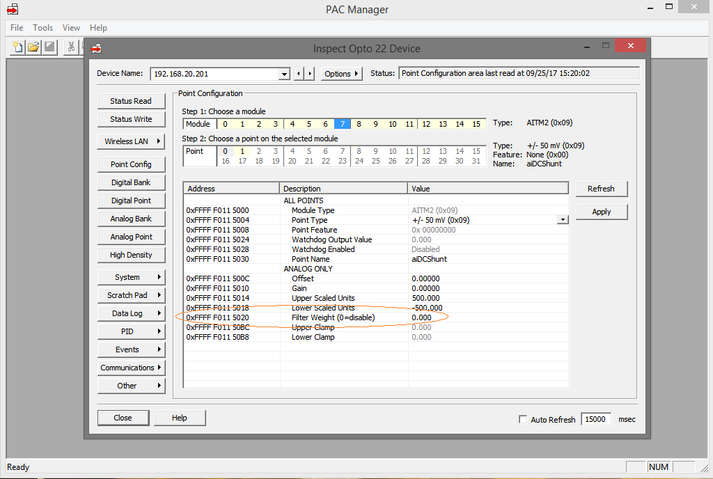
If it is just a display/graphing issue that you want to prevent, then in PAC Manager you can set a filter weight for the point which will average the value over time. Note that adding a filter will slow the response time of the point.

1 Like

0.8uA is 0.0008 mA. The specs show that the input is 100Ω, the usual problem is too high loop resistance but 100Ω is pretty low. You might try putting a resistor in series to raise the loop voltage. This might give a little more margin to the drivers in the gauge and make them more stable. 250Ω total (150Ω + the AIMA-8) will give 1 to 5V. The gauge spec should give the max loop resistance that it will drive. The loop resistance provides the voltage to power loop powered devices.

10 PSI represents 0.33% which may be more than the actual gauge resolution, it’s a pretty tight spec for a transducer. You might be seeing the limit of the gauges resolution.

You are right, thank you for correcting my math. 0.8uA happens to be the value of one “count” over the modules range.

Note that the accuracy of this module is 0.05% which (if my math is correct :wink: ) will be 15 psi for that range.

The datasheet also gives and absolute accuracy value of 10 uA. Maybe my math is off again, but .05% of the 40 mA range is 20 uA, correct?

tsopkow also said he hooked a calibrator to the module and still had noise at 8x the resolution and just within the 10 uA accuracy spec. I wonder if the reported signal would still be noisy if a stable 1.5VDC supply was hooked up direct.

Not like I never misplaced a decimal point. Most of these list a minimum voltage of around 8-10VDC. The circuitry usually uses some sort of charge pump boost to get the power to operate from the loop. The periodic nature of the upset makes me suspect that the voltage is marginal.

10PSI resolution would be 11 bits or the positive half of 12 bits which seems low for a modern sensor. most I use are 14-16 bit. Overall accuracy is from 0.5% to 0.02% for my check gauges. These are the best I could find and their total accuracy is 1 in 5000, but their resolution is 1 in 50,000. They also cost more than a grand apiece.

10 PSI is really pretty good resolution and probably exceeds the accuracy of the gauge. Mechanical gauges with accuracy below 1% tend to be pricey and fragile.

Still, the display should be steady with a simulator.

thanks msc for the suggestion. The bridge resistance of my transducer is 350 ohms and I am not sure what is is for the simulator I am using. Do you have any suggestion on the size of resistor I should try?

The accuracy of my transducers are 0.25% full scale, but the issue is the steadiness of the reading.

Thanks
Terry

The bridge is what actually measures the pressure. In order to use the input module you specified there needs to be signal conditioning that converts the mV/V output of the bridge to the 4-20mA that the input module requires. This 4-20mA loop is what I am talking about. The circuit should be from the + terminal of the input module to the + terminal of the sensor, then from the -/output terminal of the sensor to the - terminal of the input module. The sensor acts as a current source. If you are using an unconditioned bridge sensor, you will need to use a different input module.

I would try adding a 100Ω 1/4W resistor in the loop between the sensor output and the input module and see if that makes the output more stable.

Other things to look for would be the usual bad/loose connection. Current loop is pretty immune from interference but strong, changing magnetic fields have been known to couple magnetically. Some sensors are susceptible to electrical interference.

1 Like

You also can try adding a filter weight through PAC Manager Inspect. This will average multiple values and even out the noise. Start with a value around 10 - it is pretty aggressive. Don’t forget to save to flash.

I realized that part of my answer is wrong. The power for the sensor will come from a power supply that must share a common ground with the input module with the return through the input module. 12V is probably the minimum, 24V most common. In theory, the quality of the power supply shouldn’t matter too much, but if you’re seeing large voltage fluctuations from closing a contactor for instance, it might make it into the output. It helps if the negative on the rack is wired directly to the power supply rather than share a path with other loads. If you have large 24V loads, it might be necessary to provide a second power supply just for sensors.

Sorry for the earlier confusion.

1 Like

I have had time to do some more testing with this issue. Adding a resistor had no effect towards the unstable reading. I happen to have a SNAP-AIMA module and tried it. From what I can see it has the same specifications. The problem no long exists, the reading is stable.

So now what is the problem? Is the SNAP-AIMA-8 at fault or as OPTO tech stated to me it is running within it’s specifications. I don’t know if I should replace my SNAP-AIMA-8 or order more SNAP-AIMA for my application? I am running out of time.

That is interesting. This is in no way scientific, but I can somewhat confirm what you are seeing:

In PAC Manager* I brought up the count reading for an unused AIMA-8 point and a AIMA-4 point. the AIMA-8 count reading bounces around 5 counts which would represent 4.0uA. The AIMA-4 reading bounces only 1 count (0.8uA). I don’t have any AIMA modules.

Now these were unused points and have no transducer connected - this is less than ideal since who uses a module like that? I’d test with a load, but these modules are at a remote site and I have none here locally to test.

Anecdotally, I can confirm what you are seeing (at about 60% the amplitude) - so replacing the 8 channel module with another one probably won’t change much.

BTW, have you tried using the filter weight?

Please let us know what you end up doing and how it turns out.

######*Trying to uncheck Auto Refresh when you have it set for 100msec on a latent connection is fun!

1 Like

I am using only 4 of the 8 channels on the AIMA-8. This module is not optically isolated, would having open channels effect the readings of the used channels? I don’t have enough sensors available to connect all the channels to test. Is there something I could be doing with the open channels, even though I am not reading them.

Also I had tried the filter weight previously, and the number has to be so large to settle the reading and the response to change is not acceptable for my application.

Not sure here. My test above on an AIMA-4 was on an open channel, and was fairly stable. The occupied channels are measuring temperatures and CO2 readings, so they are unstable. You could connect a voltage source (AA battery or similar) with an appropriate series resistor (you may not even need the resistor on a 1.5V source with the 100 ohm input resistance) to the open channels.

Okay, thanks.

The aima-8 does not have isolated channels so you should expect to see a little more noise in the measurement. You can place a capacitor across your noisy input on the module and that should help you. Try a .01uF and move up to 1uF if needed for stability. The max refresh time on this module looks like it is just a little over 1/4 second and with it being that slow the slightly delayed response of the measurement due to the added capacitance should be of no concern.

2 Likes

The noise levels you’re seeing are not a huge percentage of the full signal range, but ideally, you may be able to do better.

Also, since you’re seeing this noise with everything disconnected except a current loop calibrator, a lot of what follows may be of no use to you at all, but then again, it might.

We also have to consider whether or not the current loop calibrator puts out a good, clean signal itself.

I’d be curious to see what the readings are from the input modules when you short each of their inputs out with short jumper wires. This will give you zero mA, but if you read the raw data, since these modules read from -20 to +20mA, you can observe the fluctuations in the raw data right near zero even though that’s below the bottom of your scaled range.

I’m just tossing all of this out there as some other things to consider:

What sort of power supply are you using to run the SNAP-PAC-RCK? I’ve found that you need to use a good, clean power supply, and it helps to have it set up to provide a bit more than 5 Volts. 5.20 Volts is often better. Power supply noise is always a consideration.

Assuming that the problem is not (or not entirely) from the SNAP-PAC AIMA-8 itself, then:

When you have multiple transducers connected to non-isolated inputs, you are, in effect connecting the commons of all of these transducers as well as their wiring together. So shielding and attention to ground loops becomes very important.

At the very low signal levels we’re talking about, it would not be surprising to see noise and ground-loop issues showing up when tying the four transducers and their wiring together this way.

Are these transducers near to, or far from the Opto 22 system input module? In other words, do you have long wire runs?

Are the 4-20mA outputs of the transducers isolated from the “process connections” of the transmitters?

Are these 2-Wire transmitters or self-powered transmitters? And if they’re 2-Wire units, do they share a common loop power supply?

Does the signal wiring run near to, and worst of all, parallel to, any high-power wiring?

Great care must me taken when designing and connecting a system like this, especially when using non-isolated 4-20mA inputs. So much so, that I almost never use anything but isolated inputs or I install separate signal isolators.

It would be very easy to end up with ground loops between transducers if they are not electrically isolated from each other.

Also, proper shielding and grounding practice is often overlooked. I prefer to use shielded twisted pair cable for transducers. Then, a simple rule that is (almost) always true is that you should tie the shield (drain) wire of the shielded twisted pair ONLY at the receiving end of the run. That means leaving it disconnected (and insulated off) at the transducer/transmitter end, and tying it to the “signal low” end at the input module (if it’s an isolated module) or to the low-side common if it is a non-isolated input module. But again, I really don’t like using non-isolated input modules.

You can use the best, most accurate pressure transmitters in the world, and still end up with noise if the wiring, grounding, shielding, and isolation are not done with great care. The loop supply(s) and how they’re connected are also important.

It may well be true that the 8-channel non-isolated current input module is inherently more noisy than the 2-channel unit.

And if the current simulator and “shorted input” tests bear that out, then there’s not much to be done other than switch to using the lower channel-count input modules.

But I’d also always recommend that people use isolated input modules like the SNAP-AIMAi, especially if they’re trying to get the absolute lowest noise, which I think you are in this case.

Noise pick-up in this kind of system can be a source of great frustration. But using isolated input modules and observing proper shielding and grounding techniques can eliminate virtually all such problems.

That was long and boring, but perhaps there is something in there that might help a bit.

1 Like