Yes it does! Indeed it was the “hex” that threw me off!
What about my questions above the modbus code? Is the way I described it above correct? What would be the modbus code for reading the integer values of F0D8 1000??
Thanks OptoMary!
Yes it does! Indeed it was the “hex” that threw me off!
What about my questions above the modbus code? Is the way I described it above correct? What would be the modbus code for reading the integer values of F0D8 1000??
Thanks OptoMary!
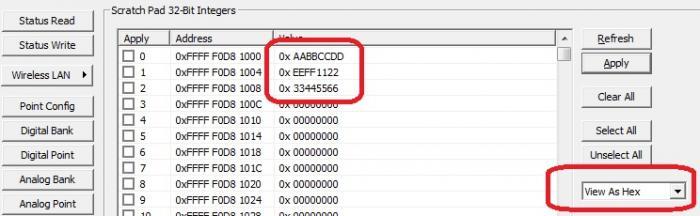
Just for clarification. We want to read address F0D8 1000 and based on our understanding we determined that these are the 6 bytes necessary to read the specified address.
0x6E
0x02
0x08
0x01
0x00
0x20
When we run this, the response we get is:
0x6E
0x02
0x04
0x00
0x00
0x00
0x00
Regardless of the state of the scratch pad variable.
Please help! Thanks in advance!
We are not sure where we have gone wrong!
I’m not sure where you’re getting these 6 bytes “necessary to read the specified address”?
To read values starting at that address at F0D8 1000, you need to convert that mem map address into to the corresponding Modbus Unit/Register which would be something like:
[INDENT]Modbus Unit ID: 110
Register Address: 2048 or 2049
[/INDENT]
as discussed in this post (click here).
Isn’t that what we did?
Based on the Modbus Guide, which can be found at modbus.org/docs/PI_MBUS_300.pdf, we believe the six bytes necessary are:
0x6E (is 110 in decimal)
0x02 (function code)
0x08
0x01 ({801} is 2049 in decimal)
0x00
0x20 (is 32 in decimal)
Is that not what we should be using?
So you’re using the same method like you used with the HDD value earlier, just with the different unit id/address here?
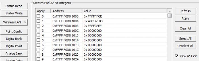
I’d try +/- 1 pm that address (so that 0x01 becomes a 0x00 or 0x02). Also, load up all the nearby scratch pad values with something non-zero in PAC manager, in case you’re just missing your values.
Otherwise, you might try Product Support again!
Hope that helps,
-OptoMary
That is correct! I did the exact same thing with the HDD module, but the unit id was 0, and then the starting address was different. Weird right?
I loaded up the scratch pad like you suggested and I still got the same result 
I changed the starting address from 0x801 to 0x800 and then tried 0x802 and the same results were produced every time. These are the bytes I got back:
0x6E
0x02
0x04
0x00
0x00
0x00
0x00
Please help!
Did you get this going? You must’ve had a non-zero Unit Id for that last one, with the HDD module, to work. Perhaps we’re using different terms here? Did you check with our Product Support Team again? (They’re the best equipped to help you sort this sort of thing out.) Sounds like you’re so close!
Hi OptoMary! Sorry it has been so long since my reply!
But I have managed to get everything running properly! Now that we can communicate effectively we can begin to build our complex strategy that we need to control our system!
Thanks for all your help!
Hiiiiiii!!! Me again! 
Hope this isn’t an inappropriate place to ask this question but, can we use pointer variables for specific memory map addresses? Like the integers we have been trying to read and write to in the brain’s memory map?
Thank you!
I’m not sure I completely understand what you’re asking here, but if you’re using those commands like “Read Number from I/O Unit Memory Map” you could pass a pointer to an integer, rather than an integer, for the address.
Is that what you’re asking? I’m not sure what advantage that would have over just passing and integer and having logic to change the contents of that integer. Could you give me more info on what you’re up to here?
That’s pretty much what we are wondering if we can do, and so I don’t see much difference either. I mean, it’s not like the pointer variable is updated as the memory map address is updated, right? It is only updated when I use the command you suggested (“Read Number from I/O…”), right?
I [I]wish [/I]there was a way to automatically move data from the mem map into a strategy variable. But alas, you’re correct, you have to call the “read” or “write” commands you mentioned to move values between the two.
I am doing something VERY similar… I already downloaded the LabVIEW ethernet drivers that communicate with OPTO 22 brain and I can read Analog values from the modules DIRECTLY into LabVIEW, In this case I am reading calibrated T type thermocouple data temperatures that were “calibrated” by using a FLUKE high precision temperature bath and running the “2 point calibration” in the OPTO “PAC manager” software to edit the config on the OPTO brain for each channel.
I get pretty good measurements and can get about 0.6 degrees (F) of temp delta between 48 channels which is much better than the spec for the thermocouple modules.
However, compared to a National Instruments PXI chassis using NI-4353 24 bit module which gets around 0.2 degrees (F) across the 48 channels and I am not even using the CJC (cold junction compensation) in the LabVIEW calibration utility (NI - MAX).
For the NI PXI, i just set the 4353 module channels to use “built in” CJC but don’t specify a seperate channel.
Is there a way to apply CJC to the OPTO 22 in LabVIEW? I don’t see any thermocouple functions in the OPTO labVIEW drivers, just Analog Input functions (Read Points).
I know this thread is a few years old but any help is appreciated!
Hello Glamourcanada,
Welcome to the OptoForums!
The CJC is built-in to the brain, so no need to do anything with LabVIEW.
Some links on measuring temperature that might be helpful to you can be fond in this blog post:
[U][B]http://blog.opto22.com/optoblog/optonews-temperature-monitoring[/B][/U] .
Also remember that our support is Free! The best way to reach them is via email: support@opto22.com.
They’d be happy to help you with calibration, CJC questions, etc.!
-OptoMary
Hi mstjohn,
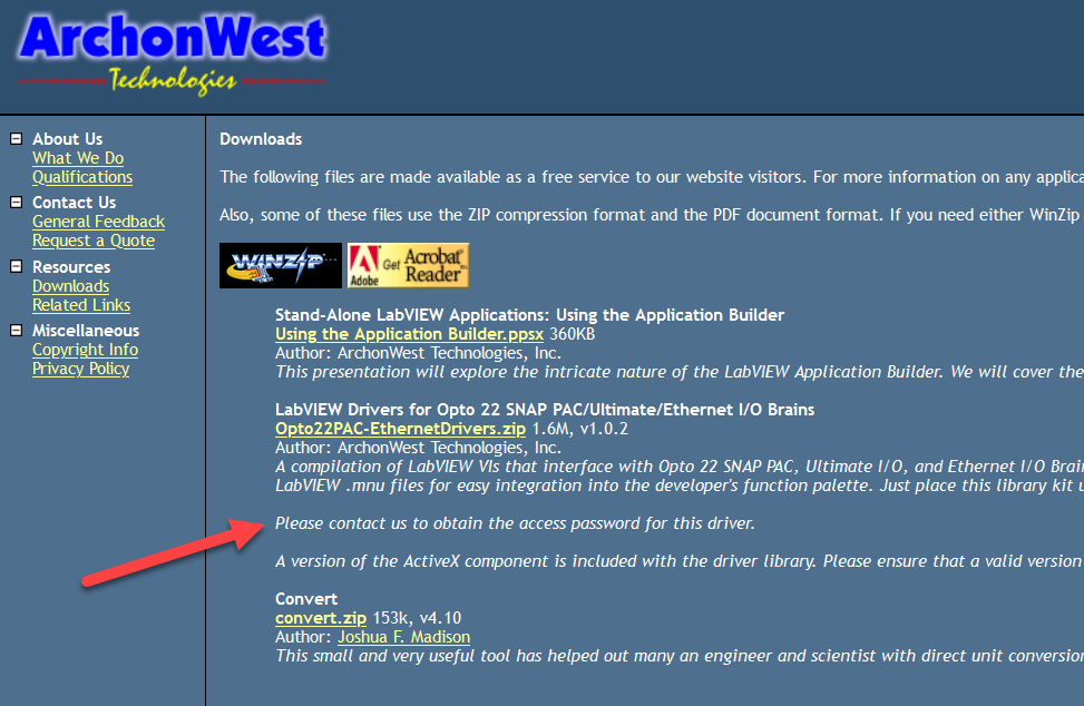
As per your guide I down load that which you suggests ArchonWest but its asking password I couldn’t open example VI .please any one help