Modbus PAC Control Groov EPIC

I have a Groov EPIC LC and I installed the " Modbus Integration Kit for PAC Control" and I am following this video Using a Modbus TCP Device with PAC Control and groov EPIC I might be missing something but my question is that I dont have the physical hardware that is communicating using Modbus TCP/IP is there a simulator I can use to emulate a device that communicates on Modbus? Any suggestions are welcome.

1 Like

You could talk to the EPIC itself on port 8502.

Ben has an example on how to use it with Ignition that has a how to lookup the modbus Unit ID (slave Id) and address:

In the Modbus Integration Kit you will use modbus registers, so add 1 to whatever address you look up in groov manage.

1 Like

So I am a newbie when it comes to this so I might be missing something here. After I installed the Ignition Modbus TCP module for the EPIC the following when I inspect the value I added ie Deg_F with a value of 0 the inspection of that using quick client in Ignition shows: Ignition OPC-UA Server|ns=1;s=[FENA-01]10.Deg_F0||[Uncertain_InitialValue] The value is an initial value for a variable that normally receives its value from another variable.|1/20/21 10:54:02 PM +00:00| Am I missing something the configuration in Ingition appears to be for connecting to a real device communicating using Modbus. Did I miss some set in Groov Manage to enable a simulated device?

No, you don’t need Ignition for this, sorry for the confusion. I was just linking to Ben’s post because he has instructions on how to look up the modbus address for the built in Modbus TCP for the controllers memory map.

To read memory map address 0xF030010C which is milliseconds since powerup:

If you set your comm handle to the localhost ip of 127.0.0.1, and the slave ID to 26 and request 2 registers starting at register 135 - you will get two registers back that when combined will give you a 32 bit integer that represents the number of milliseconds since the PR1 was powered up.
Since you are testing, you could just read a single register of 136, which will get the lower 16 bits of that register.

I don’t remember all the details of the Modbus Integration Kit, but I know it is a bit of work to figure out all the parameters needed the first time, so if you get stuck just ask.

1 Like

Here is some OptoScript on how to use the integration kit to read the from the built-in Modbus Server register I listed above, this could be called in a loop:

if(not IsCommunicationOpen(chLocalModbus)) then
  SetCommunicationHandleValue("tcp:127.0.0.1:8502", chLocalModbus);
endif

ntModbusParam1[0] = 2; //protocol
ntModbusParam1[1] = 26; //unit id
ntModbusParam1[2] = 1000; //timeout in ms
ntModbusParam1[3] = 1; //big endian
ntModbusParam1[4] = 0; //reserved
ntModbusParam1[5] = 0; //trans id - optional

nModbusIntegerType = 4;
nModbusStartRegister = 135;
nModbusRegisterQty = 2; //Note that this is in multiples of 16 bits, so we are reading a 32 bit integer, so we need two registers

O22Modbus03ReadHoldingRegistersAsInt(chLocalModbus, ntModbusParam1, nModbusIntegerType, 
        nModbusStartRegister, ntModbusReturn, nModbusRegisterQty, nModbusStatus);

if(nModbusStatus == 0) then
  nMillisecondsSincePowerup = ntModbusReturn[0];
else
  //error
  nMillisecondsSincePowerup = 0;
endif
1 Like

Thanks this was helpful. I ran into an issue where the date time appears to be backwards. Where the hour is the SS:MM:HH. A side from that do you happen to know any good way to emulate an ABB device communicating on Modbus TCP/IP to the EPIC say for example: RETA-01 - EtherNet IP (Fieldbus connectivity for drives) | ABB I ask because I am trying to mock the device to the EPIC LC and have it communicate over modbus so that I can write my application and simulate scenarios.

That ABB device looks ‘fun’.
I pulled the Modbus PDF…

The interesting bit is the ‘Parameter Access’ offset.
Would need to think about the best way to handle that based on how often I would need to change it.
Most Modbus stuff I have done has been pretty static. Get the voltage and current from a given register every second sort of thing, nothing very dynamic. The register address/offset for the voltage never changes.
I wonder if your ABB device is like that, or if it needs to change on the fly?

Other than that, it looks like Modbus. Just getting your hands dirty with the EPIC integration kit is going to stand you in good stead.
I think you will need to be prepared to be flexible once you get your hands on the device. I guarantee there will be lots of little oddities with it.
The good thing about having a standard like Modbus is that everyone can implement it how ever they like.

What Beno says here is absolutely true. You can even read the vendors documentation on their modbus implementation and still have it completely wrong once you are talking to the device. The guys that write the manuals are not the same guys creating the implementation. Modbus is the wild wild west of protocols - but you don’t have to pay a multi-thousand dollar license fee for the privilege of getting the specs for it, so there is that.

I’ve worked with some ABB drives using the built-in RS-485 RTU and they were straight forward as far as modbus devices go. I haven’t controlled them over modbus, just read the data I needed - I prefer a field wire if possible for start/stop, speed request, etc - MUCH easier in the field to have someone troubleshoot.

In my experience using modbus to control drives does not usually save money in the long wrong. I recommend buying the modules and running field wire. That way when it comes time to replace the drive and the customer no longer likes ABB, field wire is no problem, it is universal and any drive vendor can re-integrate.

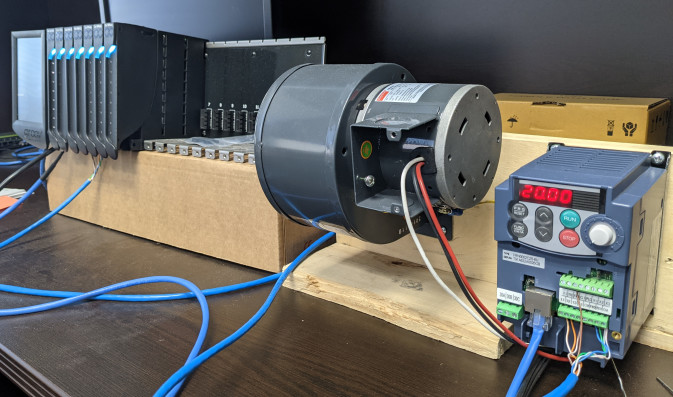
Your best bet here is going to get your hands on the device. Better yet, buy a cheap version that you can setup and have on your bench to experiment with. I have found that drive vendors pretty much use the same register layout from their little drives to their big ones. Here in the US, I like using the 120V ones so I can just setup on my desk:

image

1 Like

Thanks @philip this is my first experience with this type of programming so I appreciate the insight. I am assuming that its not really possible then to mockup and simulate a device and that we really will have to interface with a real device running modbus? My team is looking to use the ABB device to control a variable speed motor for a blower and a few other things and we are looking to the simplest and most reliable process.

You could build a mockup and simulate it, just takes time and you won’t know if you are acting like the real device or not. It is better to have the actual device. It saves development time and you know it will work on the real thing.

What sounds better - paying for HOURS of dev time to have something that might work vs spending a few hundred dollars on a real working device? I know what I would do.