Floating point variable as PID input

Hi,

I’m currently controlling a series of hydronic heating loops through a strategy running on an R1 which acts as both the Brain and I/O unit. The time delta between the moment the strategy opens a given loop’s valve + starts the pump+furnace and the moment a temperature increase is measured can sometimes be on the order of an hour. Each hydronic loop’s temperature is read from a Modbus network and stored in a table of floating point variables which are then compared against another table containing the set-points. When the temperatures drop below an associated set-point the valve/pump/furnace are activated and later turned off once the temperatures rise enough to have again reached their associated set-point.

Obviously this method creates some overshoot and very low frequency oscillations. While I probably could alleviate this by anticipating the turn-on and turn-off temperatures and having two separate set-point tables for turn-on and turn-off temperatures I feel like a set of well tuned PIDs might be even better.

I’ve never had to use PID loops on Opto22 equipment before but my understanding is that they are run at the brain level and that although they can use another brain’s analog I/O they still expect the PID inputs to come from an analog I/O point and the outputs to go to either analog or digital TPO outputs.

  • Is there any way to use the digital data from my networked sensors instead of analog I/O points as a PID’s input? Perhaps by manipulating the memory map?
  • Can a digital output set as a TPO be used efficiently through a PID in applications where the reaction time is very long?
  • If at all possible, is using PID loops the best solution here or should I just try to diminish overshoot and oscillation through other means?

Thanks!

Great question!

Short answers to your questions first.

  1. Yes. You can get the data via the strategy running on the R1. (You simply add the code into one of your charts - the PAC Control command you are looking for is ‘Set PID input’).
  2. Yes. You can set very long TPO periods. Is it efficient? Read the longer answer below.
  3. Given the long period, or long dead loop time, yes I would be looking at other methods to control your loops. (See long answer below).

Here are some (hopefully) helpful links to more information.
First up, our PID landing page. Just about every link known to Opto for our PID loops.
TPO form posts. Longish but really interesting.
PID loop technical note (pdf). Note the short section on page 4 and 5 about dead loop time.

Ok, back to your application.
Long answer is long…

Does each loop have its own furnace and pump?
An hour is a long dead loop time. I wonder where your temperature sensors are located?
Do you have one on the furnace output?
One in the room?
One on the start of the hydronic loop?
One at the end of the hydronic loop?
In other words, are there other places we can get some temperature data? Possibly with a shorter loop time than an hour.

Interesting they are read via Modbus. This means you will need a strategy to control the hydronic loops no matter what approach you chose to take (PID or chart based control).

In a nut shell, you have two challenges. First up, that very long dead loop time. An hour is a very long time in any ones life. Secondly, you need digital control of an analog variable.
In my experience, the former is going to cancel out the latter. A one hour dead loop time is even going to null and void just about any analog to analog PID control attempts.

So. Other methods…
As you say, you could have another table (or more) that turns things on and off before the set point. This will reduce your over shoot.
It could be as simple as taking your set point, and subtracting an offset value and storing that new set point in a table.
Each loop would probably end up with its own offset value, and that’s Ok.

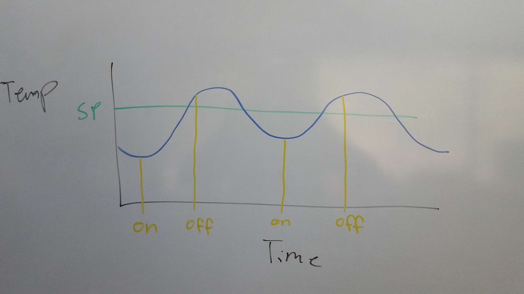
Lets take a look at what I presume is happening;

The digital control of the furnace is causing the blue line (the hydronic loop temperature) to cycle. You are seeing over shoot. (And probably some pretty good undershoot around the desired set point).
Coming up with some preemptive set points could flatten things out enough. Turning off before you hit the set point and turning back on before you get too far below the set point will sure flatten out the cycles.
The nice thing about doing it this way is that you simply take the existing set point and just come up with two others based on that one. So two more tables and very little re-writing of your current strategy is required.
The only downside I can think to this is what happens as the seasons (ie load) changes? If you get too close to all three set points in value, you could really see some cycling of the furnace.

Question. Do you have independent control of the furnace and the pump?
If so, does the current control strategy keep the pump running for a while after the furnace turns off?
I have found that there is a fair bit of stored heat in a lot of furnaces and running the pump for a while after helps even things out as the heat dies down rather than just being cut off. I have even gone so far as to run the pump all the time and cycle the furnace as required.

Another approach you might want to think about is looking at the slope of the temperature…
As you can see, the temperature is a sine wave (of sorts). Perhaps you can use this to some advantage. What I have done in the past is start two timers, one short, one long. Say, 5 minute and 30 minute (you will have to experiment a little to see what time values work best in your application and perhaps even for each loop).
At the start of the timer, you grab the loop temperature and store it into a variable. Once the timer expires, grab the loop temperature and subtract it from the first value. Presto, you have the delta of the loop for that amount of time.
So now you know how fast your heating and how fast you are cooling.
Now that you know the rate of change and over what period of time, you can use that slope to determine what you should and when.
In other words, you now know how fast you are approaching or departing from your set point. In effect, you have the basics of a very simple PID loop.

Did not mean to wall-o-text you… it really was a great question!

Hope that helps, if anyone else has some thoughts, lurk no more! Share with us!

Hi Ben,

Thanks for your detailed response. Hopefully mine will be as satisfying!

I’ll go through the PID landing page and technical note (I had already read through Mary’s PID/TPO post) but feel like I probably won’t try implementing a PID solution for this particular application.

Here are a few answers to your questions:

  • I have one central furnace and 2 pumps feeding 16 valves grouped into 8 zones. The specific heat loss of each heated zone determines the loop density requirements. In turn the maximum loop length combined with this piping density requirement dictates how many loops must be combined into each zone in order to produce enough heat. So I’m controlling different number of loops in each zone depending on their area and specific heat loss.

  • The one hour dead loop time is a worst case scenario when the water in the system is at room temperature and needs to be brought up to working temperature before being able to transfer heat to the room. During winter the water temperature will almost always be at working temperature and the dead loop time should decrease significantly. I’m guessing less than 30 minutes. The other reason why the dead loop time is so high is that the loops are located under a wooden sub-floor which doesn’t transfer heat very quickly.

  • The temperature sensors are part of a Modbus environmental sensor package I’ve designed combining temperature, humidity and luminosity. They are designed to fit inside a standard 1-gang switch/outlet box. I’ve positioned the sensor elements on the pcb to be as close as possible to the front so they are exposed to room air as opposed to the air inside the wall but it still takes a while for the air in the area around the sensing elements to reach equilibrium with the room air temperature adding to the dead loop time. I have sensors like this in every zone plus 2 outside, one in the attic, garage etc.

  • There is a temperature sensor at the output of the furnace but it is not connected to the I/O unit. It is only used by the furnace to regulate its own working temperature. I guess I could add one if it could give me better control authority though. I do not have any sensors under the floors unfortunately so besides taking IR surface readings I have no data directly from the loops themselves.

  • The pumps are currently controlled by the furnace so as soon as there is a demand from the R1, the pumps start automatically. The furnace does already leave the pumps running after the demand signal has stopped. This “linger” time can be adjusted on the furnace controller to anywhere between 5-30 minutes if I recall correctly. Controlling the pumps directly from the R1 is also an option if required but for the moment I just leave the “linger” setting to its maximum value. I should probably also mention that the pump flow rate adapts automatically to the pressure in the system so that as the valves actuate and the total system volume fluctuates, the flow in the loops themselves remains roughly the same.

Since I do not currently have any means of varying nor reading the temperatures any faster I will try implementing the 2 set-point tables/offsets solution. Once the cold season has really settled-in and the dead loop times have diminished somewhat I should have a better idea of the typical system behavior.

As you already noted, seasons (and associated outdoor temperature) will no doubt greatly affect how the system behaves so I might end up using different control loops depending on a combination of outdoor and/or furnace temperatures. Perhaps by simply varying the set-point offsets dynamically based on the furnace and/or outdoor temperatures would suffice to correct for seasonal changes? In our area the seasonal outdoor temperature differential is around +/-30°C (60°C total) although the differential during the period where heating is really required is probably closer to +10°C/-30°C (40°C total).

Again many thanks for your wall-o-food-for-thought!

The shorter answer is, that as presented, PID base simply on the room temp will never produce comfortable occupants. The natural period of the system is too long in relation to the changes in the environment.

The longer answer is contained in any number of books on control theory and especially on many written about climate control and this very topic.

What they boil down to is the concept of anticipation. As an example, given a building of a specific size and shape, the approximate amount of heat energy will bed dependent on the difference in the temperature between the outside and inside. The possible inputs, in addition to outside temp, are insolation, wind speed, occupancy and heat produced by equipment in use to name a few.

Another issue is that the floor temp is almost certainly several degrees below the temp measured in the room before applying heat. Large hydronic systems will locate the zone valves as near the actual zone as possible with the fluid circulated at working temp continuously in a loop to reduce lag. They also have temp sensors in the inlet and outlet of the zone.

A simplified system might start with maintaining the floor temp as measured at the zone outlet at a temp differential with the desired room temp that would change as the outside temp and conditions changed with this differential controlled by a PID loop. The maximum differential should also be limited for comfort and to control overshoot. This would be an example of cascade control.

Also, remember that the temp will rise no faster than the available heat input will allow nor cool faster than heat can be shed to the outside. This will largely govern step response.

To All,

Don’t forget that the PID loops in Pac have an issue if you’re using prior to 9.5 and you’re using an input from the controller. It can over overwrite the value and make you go crazy tuning it. If you’re in 9.5, don’t use the “obsolete” loops unless you’re system is already tuned to them from prior versions.