Hello,
I am controlling the pH of a continuous process (DAF unit).
Currently, the pH probe is sending a raw mV value to a transmitter.
The operator is typing in setpoints for the 4-20 mA output to the transmitter
(example: 0 RPM = 4mA = 7.2 pH, Max RPM = 20 mA = 8 pH)
This scaled output is being sent to a dosing pump that accepts a 4-20 mA signal and as a result lowers the pH until it reaches 4 mA, when the pump stops.
I want to only use the transmitter as a local display, and send the 4-20 output to a groov RIO (scaled for 0-14 pH instead, to get the actual pH value to the RIO)
Then I would like to output a 4-20 from the RIO to the dosing pump.
Doing it this way would allow 2 things:
Remote monitoring of the pH, and also now can alarm operators when pH goes out of range
Allow operator to enter a setpoint from groov view, so they do not have to dig in the transmitter or dosing pump menus.
I am a bit stuck on the best way to implement this. I started by just taking the 4-20 output of the transmitter to the RIO, and scaling it from 4-20 mA to 0-14 pH.
I have considered using a PID instead of this method described above, but I’m unsure how to even start getting the correct values / scan time, and some Googling has told me that pH is a difficult variable to control with a PID due to its highly nonlinear curve, and also because we have a varying influent flow rate.
Any tips or pointers in the right direction are greatly appreciated, because it’s making my head hurt
What you describe is proportional control (The P part of PID). You can do that directly with the RIO by setting up one of the PID loops.
Setup your input and output scaling:
Input 4-20, 0-14pH
Output 0-100%, 4-20mA (RIO scaling would be -25% to 100% for 0 - 20mA output)
Configure a PID loop as follows (to duplicate the proportional action you described)
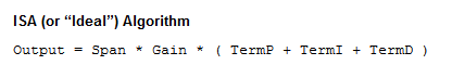
Set Algorithm to ISA
Set the input to your pH input channel with low range 0 and high range 14
Setpoint will be host
Set the output to your dosing pump output channel with lower clamp as 0 and upper clamp as 100
Set feed forward to 50 and feed forward gain to 1
Save the PID config
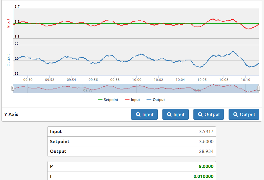
On the PID chart window set the P term to 17.5 and your setpoint to 7.6 - that should duplicate the control action you described above.
Now you can fine tune to eliminate offset by lowering the P term a bit and adding a small I term.
@aallen Are you using or planing to use the Node-RED dashboard in the RIO to build a simple operator interface? I’m thinking a simple graph would really help tune this loop, or are you going to have the operator use the groov Manage interface and view its graph?
@Beno ,
I will be using groov View hosted on my Epic.
Node-Red will read the setpoint input by the operator in groov View, then write it to the RIO’s MMP address that I’ve configured to be the setpoint for the PID.
I’ve setup a test groov View page for myself to tune the loop with
Ah, gotcha. Nice. I was not sure there was an EPIC in the mix…
Whats the thinking behind setting up the PID in the RIO then over setting up the PID in PAC Control?
The RIO will need to be standalone at some point?
Not using a PAC Control strategy?
My thought process was to share the processing load since the RIO wouldn’t be doing much otherwise.
Would it be more beneficial to do it in PAC Control?
No, I think your logic is sound. Also that way if your network connection goes down between the RIO and the EPIC the PID will keep going with the last set point…
I was just asking to try and understand your setup and both make sure we were constructively helping and I’m also very interested in how our gear is used the the end users thought process around how they chose to use it they way they do.
You’d probably not be surprised how many forum posts and blogs I do that stem from customer questions/feedback.
I chose ISA over velocity for proportional control because ISA is not dependent on the initial conditions. Given a setpoint and input, it will always produce the same output. Also, feed forward and gain is broken on the velocity algorithm so you can’t use them (I’ve reported this multiple times).
If you want to use a PI or PID loop, then I would prefer velocity over ISA for the bumpless behavior on setpoint change and the ability to command the output while the PID is running. However, with velocity you need to pay attention to the startup conditions (set an initial output).
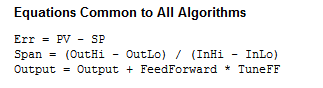
Here are the algorithms in the help file:
Your proportional range is 8.0 - 7.2 = 0.8. This is the change in input (Term P for ISA) that would result in a 100% change in output. Your Span is 100/14. Knowing that, we solve for Gain (which is the proportional tuning parameter).
Gain = Output / (Span * TermP)
Gain = 100 / (100/14 * 0.8) = 17.5
The purpose of the Feed Forward is to provide bias on the output of 50% when the input is at the setpoint.
If the RIO is setup as an IO unit in PAC Control, then generally you should setup the PID settings in PAC Control. It will still run on the RIO and continue to function if the RIO is disconnected from the network and you avoid the risk of PAC Control wiping out your PID settings on first run.
If the RIO is setup as an IO unit in PAC Control, then generally you should setup the PID settings in PAC Control. It will still run on the RIO and continue to function if the RIO is disconnected from the network and you avoid the risk of PAC Control wiping out your PID settings on first run.
Thanks for the heads up. It currently isn’t an I/O unit in my PAC strategies, however, I will keep this in mind if it is ever necessary. I wasn’t aware it would reconfigure PID loops to default also, so I would of been annoyed when it happened lol.
It won’t by default, but its one of those grey areas that becomes comes clear with experience… and Im sure you know the definition of experience… Experience is just saying "I broke that already"
Not sure how tight of control you need, but here are some considerations.
If the influent flow rate is measured - consider using the flow rate to drive the injection pump speed and setup the pH PID output to calculate the injection rate per unit influent. That way your PID isn’t thrown out of wack when the influent volume changes.
If the influent pH changes a lot, then measuring the pH of the influent could also be used to determine the injection rate while the PID is used to trim the value with the effluent pH.
Thanks for the detailed instructions and initial conditions!
Took a while to implement and test due to other issues that came up, but after tinkering with it for about 40 minutes it’s somewhat stable. (with this influent mixture at least )
I do have an additional question now that it’s up and going. We shutdown overnight and don’t operate on weekends. Is there an easy way to stop or pause the PID? Does it matter if the scan count gets too high, or does it reset once max number of scans is reached? The operators are turning off the dosing pump when they leave, but the RIO is still trying to send an output to it.
I’m not sure you actually need to ‘turn off’ the PID. The scan count will just keep ticking away regardless.
It will roll over at some point in the future, but its not a concern. Its really just there to let you know that the PID math is happening as it should.
If you want to you can always just click on the ‘Mode’ (just below in your screenshot) and set it to Manual, but you will see the scan count keep on counting as manual only disconnects the output from the PID math.
If the PID has a slow response time, then it will take a long time to recover from being saturated at 100% or 0% output - this is likely to be undesirable.
Is there a way to put that control into groov View, so that the operator will be able to turn it off as he is shutting off the system? They don’t currently use groov manage for anything other than to get to View
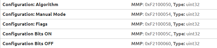
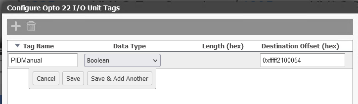
Yes. This is the area you want.
Note at the top of that page you can select the PID loop number, as you do that, all the addresses change.
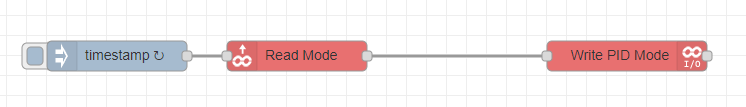
So just dial up the loop number you want and then get the Manual Mode address and put that into your Node-RED flow.
You will then have a button in groov View that writes to Node-RED that sets the MMP address.