Read and write I/O value on an opto22 R1 brain with labview through ethernet

Hello everyone,

For a project, I would like to use an opto22 as a DCS and a PC host with labview to command & control a cooling system.

I have a R1 brain with some analog and digital I/O and I would like to read and write these with labview in order to command & control & loggin it. I made a first try to communicate with opto22 with ethernet modbus/tcp and it has been a dead end.
Is there a way to communicate with R1 brain through ethernet and labview (12 sp1) ? If someone could give me a Vi example which works or explain me how I can do it.

Best regards,

Loic.

Hi LoicCAS,

Welcome to the OptoForums!

Check out this ArchonWest download [click here].

Here’s a related discussion that might also be of interest.

-OptoMary

Hi there,

I’m trying to do something similar as well. I checked out the ArchonWest downloads and even spoke with JC. Unfortunately I am an inexperienced user of both labview and the opto22 system and since there was no documentation on the ArchonWest files our lab decided to just directly code our needs.

The end goal of our needs is to have our SNAP-PAC-R1 run various strategies that we could initiate/terminate through labview.
That being the end result, it is my job to begin this process. So I am trying to just force the first coil on my SNAP-IDC-32D located on module 2.

I’ve been looking through the opto documentation on this sort of thing as well as the modbus protocol documentation. I know the command coade for this is 05, but I’m unsure of the slave address and subsequent bytes that follow.

Again, looking through the documentation I believe that the address is the (module number)*64 + 513?

Any information or assistance would be greatly appreciated!

Thanks in advance!

Hi Francesco,

Welcome to the OptoForums! Before I get too far into the details, let me just clarify a few things you mentioned. It sounds like you’re trying to communicate from LabView using Modbus/TCP to a SNAP-PAC-R1 which has a SNAP-IDC-32D in module 2, which is all well and good. However, I’m concerned that you said “trying to just force the first coil…” That module number you mentioned is an INPUT not an OUTPUT. Perhaps you also have another module on there?

I’m also a little unclear about what you mean when you say you’ll have the: “…SNAP-PAC-R1 run various strategies that we could initiate/terminate through labview.” That SNAP-PAC-R1 is a controller which can run what we call a “strategy” (program) which you create using or PAC Control software. Is that what you mean when you say “various strategies”?

In any case, I strongly recommend you get our free PAC Manager tool (click here) if you don’t have that already. This tool with let you read (or write if you have an output) to/from those modules and see their Memory Map addresses. PAC Manager also includes a tool which will help you convert a Memory Map address to a Modbus address.

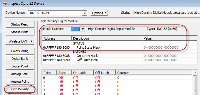
For example, in this screen shot of the PAC Manager screen in: Tools > Inspect > High Density, I see that all my inputs are off:


I also see that Memory Map address F1808000 holds info on all the points on that module in slot 2 (as a bitmask). With that address, I can convert to a Modbus address, as described in this post (your “Modbus master” would be LabView – and you have no “part C”, your mem map address is something like F180 8000 vs. the F0D8… address shown in that example).

Your Modbus Unit ID & Register Address should come out something like:
[INDENT]Modbus Unit ID: 194
Register Address: 16384 or 16385[/INDENT]

assuming I have all your info correct above.

Also keep in mind that our Product Support is FREE! And they’d be happy to help you sort all this out.

-OptoMary

Hi OptoMary,

Thanks for your response! Sorry it has taken me so long to reply!!!
You are correct in many of your assumptions and my language in my first post is HORRIBLY wrong. Very sorry about that.

We are trying to read the state of specific, and eventually all, channels on our SNAP IDC-32D to which we are applying voltages in the given range to change the state from off to on.

Ideally we would be able to read all of the states of each channel on the module.

What modbus command would we need to do this? We believe it is command code 04? We are able to read the counter value and have that counter value returned, but not the actual state.

I’m looking at 1678_Modbus_TCP_Protocol_Guide and it was suggesting we need to read register 513, which is 201 in hex. This is what we tried to read and got a return value that was the counter value. On this page we are looking at of the guide, which is page 36, there appears to be two different configurations? Register 513 is listed in two separate instances on the table on this page. It’s a little confusing. Any help clarifying this would be very welcomed and appreciated!

I’m not sure if I should call your product support line or just continuing here. Either is pretty acceptable for me. Perhaps I’ll try calling as well. Your thoughts would none-the-less be greatly appreciated!

I’m glad you’re looking at from 1678 and have read a counter value. The Counter Data is stored in the “Input Registers” (which corresponds to the “command code 04” you mentioned). That other column on page 36 is for “Coils,” which is a different command (01 instead of 04), with the same 513 “register/coil” so I suspect all you need to do is use that different command 01 to get the state!

Hi OptoMary,

Thanks for your quick response!
I tried that, but alas to no avail!

I’m also using the Modicon Modbus Protocol Reference Guide and on page 24 it has the function information for code 01 and it provides a sample query.

Since the register is 513, which converted to Hex is 201, the data I’m passing that is pertinent (or at least what I believe to be, perhaps you could confirm?) is the Slave Address which is 0, the Function which is 1, the Starting Address Hi is 2, Starting Address Lo is 1, No. of Points Hi is 0, and No. of Points Lo is 2. I believe No. of Points Lo is 2 because I need to read registers 513 and 514. Is that right? Perhaps I’m missing something?

The result I get from the TCP Read in labview is a string that I convert to an unsigned byte array. The resulting array is [0,0,0,0,0,4,0,1,1,0].

I have a power supply running 3 volts at very low current across pin A0 and ACOM and I’m using the PAC Manager software to verify and watch live as the state changes from on to off as I turn on and off the power supply. I’m running my labview program a couple times while it’s off, then turn on the power supply and run it a few times again, trying this back and forth a number of times but nothing changes. The unsigned byte array always returns the same values.

We have a working send/receive LabView VI that uses Modbus/TCP with an Opto22 enet 100 which works. I’m basically using those VI’s and changing the modbus querry values in an attempt to get the desired response - a 0 or 1 to indicate that the channel is off or on respectively.

I’m hoping I’ve provided enough, perhaps too much, information to allow you to help me out! :cool:

If there is anything else you’d like to know just ask. I can provide images of our VI’s or anything else you need!

Thanks in advance!!!

I should probably also note that I tried code 2 as well and the unsigned array is almost identical, but instead I get[0,0,0,0,0,4,0,2,1,0]

Sounds like you could use some help from our support team (click here) – they have loads of experience with Modbus, not sure about LabView.

I’ve been in contact with them, sort of helpful. Some good came from the situation as I have since figured out how to read the registers on my SNAP IDC-32D to determine the state of each point.

The next task I must complete is to create a variable in my strategy and then be able to read it and change it as necessary. We’re guessing there will be a certain part of the memory map that this defined variable is stored in and then we will somehow be able to read it and write to it. Is that a safe guess? Can you shed any light on this?

Thanks in advance!

Not exactly. If you create a variable in your strategy, it does NOT have a place in the memory map automatically. However, from your strategy you can read/write to the scratch pad areas of the mem map (for strings, integers, and floats). That’d be your best bet for reading and writing values into your strategy via Modbus. Check out the PAC Control commands under “I/O Unit - Scratch Pad.”

Sweet! Thanks!!

Also, will I be required to have something in my strategy that reads the scratch pad every so often for the strategy to detect a change? I’m guessing I will.

Yes, the scratch pad and strategy variables can’t be automatically linked somehow (I wish they could!) so you’ll need to have a looping chart periodically check/update. Consider adding a delay in that loop of at least 1 ms (longer if it’s reasonable) so that your CPU won’t be swamped with constant/unnecessary reads.

HA! At least? I doubt we’ll need to be having it checked that frequently, probably on the order of minutes!

Thanks a LOT OptoMary! Super helpful! :smiley:

I’m back with another question:

One of the PAC Control commands is “Set IO Unit Scratch Pad Bits from MOMO Mask”

What’s a momo mask?
Is this the command I would use to turn a bit from a 1 to a 0 or vice-versa??

Slightly more thorough details of my needs:

I see from form 1465 that scratch pad bits have the starting address FFFF F0D8 0000, and then the next 127 bytes are also allocated for use as individual bits to be read/written to/from. (Confirm please? :D)

Suppose I wanted to change the second byte, thus addressed at F0D8 0001, to be (in binary) 00110101. What if I wanted to change the second byte to (in binary) 00000001. How would I go about accomplishing these tasks? The set command in control basic doesn’t specify memory map addresses and so I’m a little confused. Clarification would be greatly appreciated! :smiley:

To answer your first question first, a MOMO Mask is a “must-on must-off” mask. At address F0D8 0400 you write (or the command does) a mask where each 1 bit means “set this bit” and the bits that are 0 mean “don’t change this bit.” Then the next 8 bytes are for “clear this bit” for a 1 bit and “don’t change” for a zero.

However, I strongly recommend you avoid packing your data like that, if you don’t have to. Because, here you’re talking about bits and bytes but the controller has lots of memory which is mostly divided into 4-byte pieces (an int 32) for your data.

Later in the Scratch Pad area you’ll find a bunch of these int32 values at address F0D8 1000 (1024 of them) then an even bigger later one where we added even more. The commands you’d want to use in PAC Control start with “Set I/O Unit Scratch Pad Integer 32…” or “Get I/O Unit Scratch Pad Integer 32…”

I would do this even though you might not use the highest 31 bits of each of those Integer 32 values. Because, it’s probably going to save you some programming time, might be easier to understand, and–since you’ll have less bit-packing code–may even run faster.

I hope that helps!

-OptoMary

Thanks OptoMary! That was very helpful!

So I’m taking your advice and writing integers to the scratch pad, it seems that it will suit my needs and be a lot easier then figuring out individual bits.

I was successful in changing the first integer, at the address you suggested, to a non-zero value. Now I need to read that using modbus command codes. I’ve determined, using the modbus calculator in the PAC Manager that my unit ID is 110(6E) in hex and the register is 2049 which has a Address Hi of 14 and an Address Lo of 31. I’m guessing I’ll use command code 2 with No. of Points Hi being 00 and No. of Points Lo being 32(4 bytes)? Can you confirm this?

I’ve since done some more testing and had some weird results and things that raise questions:

So I’ve been using your calculator and using form 1465. Form 1465 is slightly confusing. It says that F0D8 1000 is Scratch Pad 32-Bit integer element 0 and that it’s length is 4(hex). 4 hex digits represents 16 bits, so how does that equate to a 32-bit integer? Is it a 16-bit integer? the memory addresses increment in 4. Are they four bits or four bytes or four hex digits? If it’s four in hex that would be two bytes, would it not?

I recognize that 2049 should be converted to hex, which is 801 in hex, and then I use 8 as my Starting Address Hi and 01 as my Starting Address Lo, not as described above. I mean I tried both but neither was successful.

Can you please help clarify? Thanks in advance!

The lengths mentioned in from 1465 are bytes. In the case of the Scratch Pad 32-Bit integer elements, you have 4 bytes (or 32 bits).

If the length value is greater than 9, then hex vs. decimal representation would make a difference. In this case, since 4 in decimal is the same as 4 in hex, the “hex” was just throwing you off. (Vs. if the length was, say, 40 or 0x40 hex which would be 64 in decimal.)

Does that clarify?