I have been studying the use of the PID loops on Opto PAC EB2 units. I use the OptoMMP to interact with the EB2 units as we run from Linux using custom code. We have successfully interacted with digital and analog modules through this interface. We have not attempted using the PID loops. Reading through the limited documentation (OptoMMP Protocol Guide is the only one I have found) on this area I still have some questions. I’m not concerned with how to tune loops or anything associated with the operation of the loops. I have questions about the PID status flags and status bits.
I read on page 176 that the status flags can be read at address 0xF200002C. Address 0xF2000030 has the following text “Status bits ON. Used to control individual Status flag bits. Write a 1 to turn the bit on.” Address 0xF2000034 has a similar text “[SIZE=1][SIZE=1][FONT=Verdana][SIZE=2]Status bits OFF. Used to control individual Status flag bits. Write a 1 to clear the bit.” I am assuming that all of these addresses are really meant to be read and not written to as the text might imply. This assumption is based on the what seems to be a regular operation of putting all the read only addresses first and then following with the write addresses. Addresses 0xF210005C and 0xF2100060 have similar but the same words as the previously mentioned addresses “[FONT=Helvetica][SIZE=1][FONT=Helvetica][SIZE=1][FONT=Verdana][SIZE=2]Configuration bits ON. Used to control individual Configuration flag bits. Write a 1 to turn the bit on.” and a similar one for OFF.[/SIZE][/SIZE][/FONT][/SIZE][/FONT][/SIZE][/FONT][/SIZE][/FONT][/SIZE]
[SIZE=1][SIZE=1][FONT=Verdana][SIZE=2][FONT=Helvetica][SIZE=1][FONT=Helvetica][SIZE=1][FONT=Verdana][SIZE=2]A couple questions: Are my assumptions correct? Is there anyone else out there programming using the OptoMMP Protocol?[/SIZE][/SIZE][/FONT][/SIZE][/FONT][/SIZE][/FONT][/SIZE][/FONT][/SIZE]
While we chew over your question, I just want let you know that I moved your post… It is more of a software question that an example or snippet of code, so this is a better place for it…
Great question. Took me back in time to when I last looked at this area… Gota love stretching those rusty memory brain cells…
These areas are a little different, so feel free to ask any questions if the following is not clear…
From page 176 of doc 1465, the OptoMMP Protocol Guide;
F200002C is a read / write area were you can read what the current status is on the PID loop.
If its all good, it will be 0. If the input is below the input low scale, it will be 1, if above, it will be 2 and if the output has been forced to a user level because the input is out of range, it will be a 4.
Anything other than those three values will be ignored.
Since the PID is writing to that memory address every PID scan loop time, if you do happen to write anything there, it will be over written. (So yeah, writing anything there is a little pointless, but my point is, you can write to that address).
If you put the PID in manual and turn off the algorithm (F210 0054 and F210 0050), then you can set and clear those bits from address 30 and 34.
Why would you do this?
The main reason is to test any code that you may have in place that checks this address and actions any bits that might be set. For example, your custom Linux code might read address F200 002C and if the output has been forced, then send an email alerting a user of this fact.
You can test this email function then by turning off the loop and writing to the location.
Same deal then with the configuration flag memory locations 58, 5C and 60.
You can read and write to 58, but if you want to write to it without doing a read first, you can just write to 5C and it will add your value to the value in 58.
Same with turning configuration flags off, you could do a read of 58, subtract what ever its going to take to change it to the value you want, or you can just write the value to mem map 60 and it will automatically do the subtraction/addition for you.
I was able to test all of the above by using PAC Manager.
I know you said you are using Linux (and I am a huge Linux fan), but if you can run PAC Manager on another PC or Laptop on your network (or try running it under Wine or Crossoveroffice) I think you will find it very helpful in testing and setting up your MMP code…
I simply fired up PAC Manager and took a deep dive into the manual and the MMP addresses on the PAC R Controller PID Loop area.
Only took a moment or two to understand that the manual was right (granted, a little vague perhaps) because I could change all the values and see the results in real time.
Thanks for the insight! I have a Windows machine that I normally use and that I can put PAC Manager on. I will definately do that. I’m just at the beginning of this so I’ll need to tinker with the system a lot to make sure I understand how everything works together.
Just wanted to second the plug for PAC Manager, a must for anyone tickering with OptoMMP.
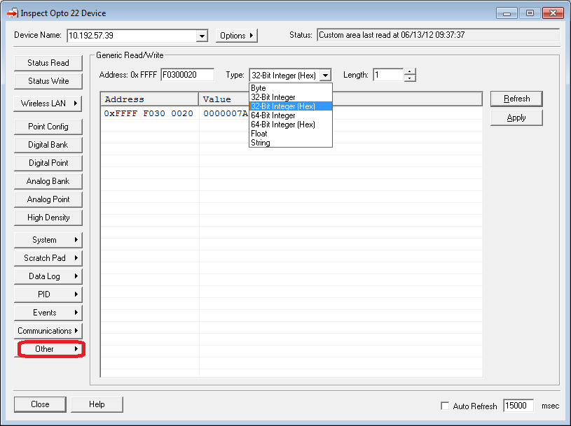
For this case, you’ll want to do Tools > Inspect (or just click the little magnifying class Inspect button) then click PID to see all those values in an easier-to-read fashion.
For further tinkering, (also under Inspect) click Other > Generic Read/Write which lets you select the type/format for your data there in the drop-down. I use that all the time when I’m Mem Mapping!