Leeveney,
The answer to your question is the answer to a different question…
The REAL question is; how do you have the PID set up on the I/O unit?
IF your input and output are on the same I/O unit AND your P, I, D and Setpoint are not calculated or adjusted by the strategy in any way, AND if you have the I/O unit configuration saved to flash, then your PID loop will run as long as the I/O unit has power.
In fact, if the unit powers off and then back up, and your PID loop is set to auto, then the loop will start running and keep running with no other assistance needed.
The ability to save your PID configuration to flash is one of the most powerful features for the typical PID user… Knowing that as long as the rack has power, the loop is controlling the output, is a real stress saver let me tell ya.
The key is, how to save the settings to flash… Let’s take a look at two ways that I have used over the years…
First up, using PAC Control to configure and save your PID settings.
Here is a screen shot of the PID loop config in PAC Control:
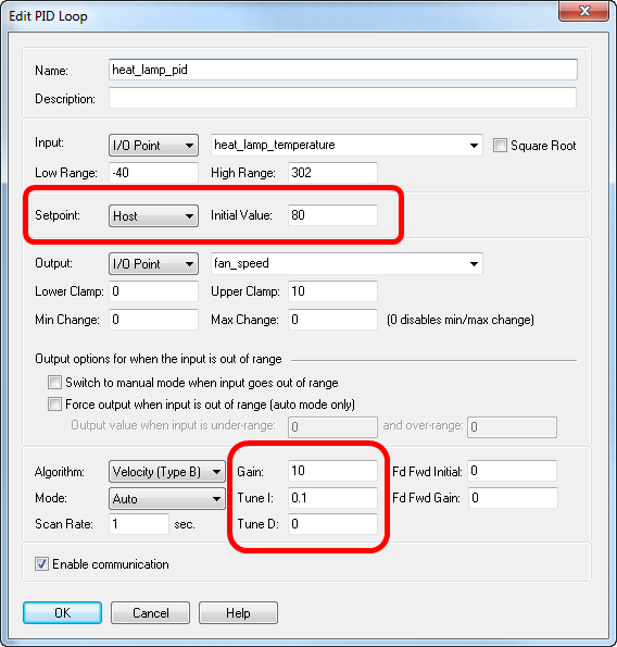
I have highlighted some (IMHO) really important areas.
First up, the setpoint. You need to set this value to what you want. DO NOT leave it at the default zero that it starts out at. (More as to why in a moment).
Next is the values for P, I and D. Put some values in here to get you started.
Once you have configured the loop here, do a download, run the strategy, and then open up the PID loop in configure mode.
Use the nice graphical tool to tune your PID loop.
HINT. You can open more than one instance of the graphical tuner for any one PID loop. This can be really helpful if you use different time axes to help tune the loop.
Once you have the loop tuned the way you want, hit the ‘Save Tuning’ button.
Here is a screen shot of what you see when you click the button;
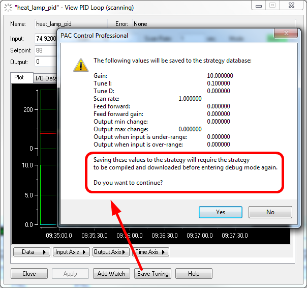
Take a good close look at the bit that is circled… It’s important you understand what this means. (More in a moment).
What DON’T you see in this dialog box?
There is your P, I and D, there is scan rate, feed forward settings, output changes, input over and under range settings… it’s all there, right? No. Not exactly, there is one important bit missing:
the setpoint.
Since the setpoint may well be calculated by the strategy, and thus it might change, it’s left out of the ‘save tuning’ process by the clicking of said button…
What’s the answer? Simply make sure you add it when you configure the PID loop the first time, just as I mentioned up the page a bit.
Let’s take a moment and see what’s going on here to better understand this whole process.
When you configure a PID loop, that configuration is sent to the I/O unit when you run the strategy on the controller the first time.
Each time after that, the controller looks to see if the configuration it has matches the configuration on the I/O unit. If it does, the configuration is not sent; the strategy just picks up and runs.
If, in config mode, you change the P, I, D, Setpoint, or any of the PID settings, when you download, the controller will see that change and it will send the new PID configuration to the I/O unit. When you hit the ‘Run’ button, the controller and I/O unit will start working with the new settings.
This is why, once you click the ‘Save Tuning’ button in debug mode, you are then required to compile and download the strategy again.
Even though you have not made any changes to the strategy, you have only changed the tuning parameters of the PID loop… they still need to be sent down to the I/O unit.
Let’s break this down and make it a bit more real-world… Let’s take the screen shot examples. See in the first screen shot, the gain is set for 10.
Ok, now in debug mode, I tune the loop and end up with a better value of 5. I click the ‘Save Tuning’ button. I will then see that new gain value of 5 in the save tuning dialog box.
If I then go back to debug mode and open that PID config dialog, I will see that new value of 5 there as well.
Pretty cool. Next time I download and run the strategy, those new values will always be sent to the I/O unit and my loop will always run with the new and improved values that I worked out for them.
This is why you need to put your required setpoint in the config dialog.
Ok, but what if your setpoint is calculated. What then?
Two things happen. First up, you still should put an ‘Initial Value’ (just like the config dialog says) in when you first set up the PID.
DO NOT leave it at zero. Why? Because when you click that Run button and start your process, the PID loop will take zero as its setpoint and try and control for that. Your charts will also start running, calculate your setpoint, send it to the I/O unit, and your PID will then ‘slam’ from a setpoint of what ever it was before you ran the strategy, to zero, then to what the new calculated value is. Not good.
Ask me how I know this (think water hammer on an 18-inch diameter suspended pipe).
Yeah, you’re right, your initial value may not be the same as the strategy calculated value, but I suggest that if you leave it at zero, it will be even further away from the calculated value!
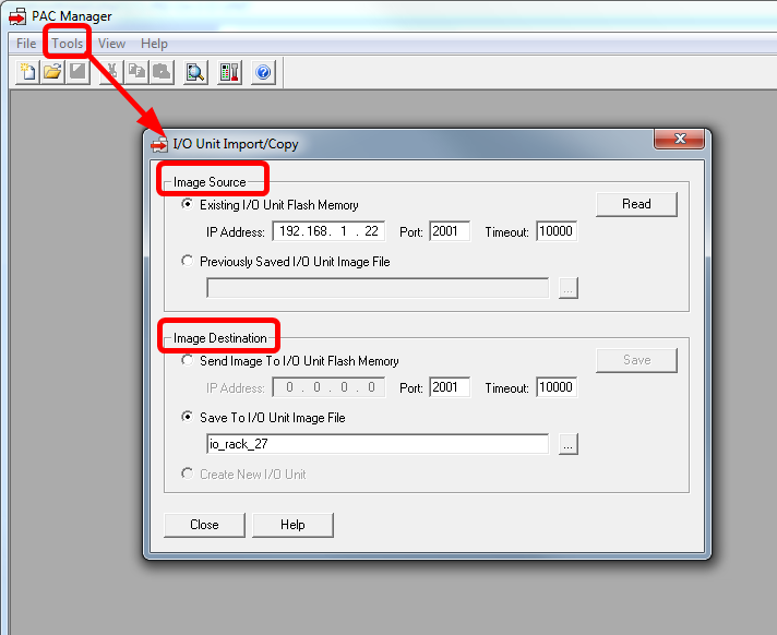
Ok. So once you have got your PID loops tuned and are happy with all your values, the last thing to do is to save the configuration to flash.
Do this from PAC Manager.
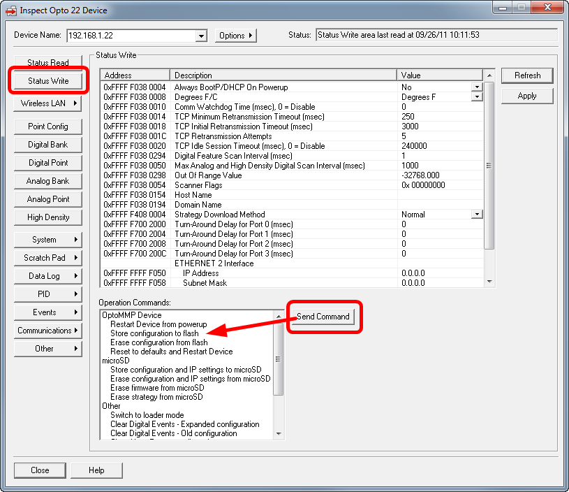
Now you can rest easy knowing that if your I/O rack has power, it will run its PID loop(s) with good tuned values.
You also know that if you have a network failure at the same time as a power cycle, the I/O rack will power up with good tuned values, even though it will not be talking to the controller. (If you really do need that calculated setpoint, then don’t bring your loop up in ‘auto’ mode).
Right, so that takes care of setting your PID values from PAC Control. What’s the second method I used to set them up?
Do it from within the strategy.
The way we had things set up at the hospital was that we tuned our loops from PAC Display, not the graphical tuner in PAC Control.
This meant that we had to ensure that the P, I, D and setpoints were saved to the flash on the I/O unit now and then.
We did that via a bit of OptoScript:
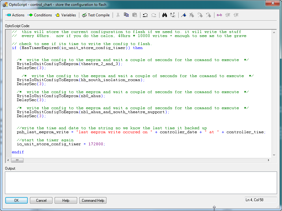
(BTW, the flash is good for around 300,000 writes)
But wait, not so fast… there are two gotchya’s.
-
When you save the config to flash, the I/O unit goes off line for a moment. You will need to make sure you are running some sort of I/O enabler chart (which you should be doing anyway).
-
What happens if you do a firmware upgrade or have to change out that I/O unit for another?
Where are your settings then?
It is up to you then to periodically copy your I/O unit to an image on your hard drive (and then back up those images!).
(More on this cool feature in another thread).
So, yeah, Leeveney, long answer I know, but I hope that you now see that the answer to your question really does depend on the answer to the real question. And that is: It depends on how you sent up the PID loop in the first place.
Do it right and your PID loop will loop the loop for a very very very very very very very long time!
PID_on!
Ben.