Any PID + TPO users out there?

Hi All,

I’ve just been looking at some options for having a digital TPO as the output of PID, and am wondering if/how/where all you OptoForum users out there might be doing this.

For example, what controllers/brains do you have in the mix?

Do you use a SNAP-AOD-29 module or a digital output configured as a TPO?

Any/all examples and details you can share will be helpful to me.

Thanks!
Mary

Hi Mary
If you have seen my (prepare for shameless plug…) customized Opto22 controller based web server demo, the hot water PID loop is based on a TPO output. I created a PID loop which takes the output and writes it to the TPO of a digital point. I have the period of the TPO set to 1 second (from memory) and it works pretty well. I use an R2 as the controller, a SNAP-AIRTD and a SNAP-OAC5-i.

I have also done this with a warm room for harvesting pathogens for the ballarat base hospital. It is a small room that has a 2400W electric heating element. There is a PT100 temperature sensor mounted on the wall and the room is heated to maintain 36degC. I use a SNAP-AIRTD module for the input and a 240D25 SSR driven by a SNAP-ODC5-I for the output. The PID is configured on a SNAP-PAC-R2 controller with the TPO period being (I think from memory) 4 seconds. The PID loop is really slow but it maintains the room temperature to +/- 0.5degC which is more than adequate for the pathology department. It does suffer from overshoot if the room has been allowed to cool but it gains control pretty quickly.

Nick

1 Like

We have a ‘soft’ PID loop and TPO on a digital output which we used on an Ultimate and even carried it over to a PAC R1 for a while. We use it to control the temperature of a small chamber (20-30 litres), our controlled thermal input is from a from a heater with measurement from a Type K Thermocouple. This maintains temperature at around 80 deg C +/- <0.5 deg C, however, when the RF is switched on, there is basically so much heat absorbed by the chamber and load that we cannot dissipate it quick enough, we can use quite a bit of RF in the process and may get a temperature rise of 10 - 15 deg C (as much as 300 watts of RF depending upon process).

We do get overshoot, not so good on heat up from cold, but is acceptable as it enables us to get to our target temperature faster when cooling (to do with the thermal mass of the Chamber load).

We have not bothered with PID modules as we generally have spare dummy outputs we can use for the software PID.

Hi CeeJay,

I’m glad you mentioned the “dummy outputs” because that was one of the aspects of configuring a PID w/a TPO output that puzzled me when I had a look the other day.

The PID logic (including where the output is sent) can all be self-contained within the PID, no “dummy outputs” or extra logic required. In fact, you don’t even need a strategy or a controller, since the PID loop logic is all handled on the brain.

For example, I might want my “main” strategy to run on a PC with SoftPAC, but have some distributed I/O logic elsewhere – such as a brain (maybe a SNAP-PAC-EB2) running a PID. But I might NOT want to have an extra chart in SoftPAC to move the output of that remote PID to the remote TPO digital output point.

If the whole PID is self-contained on that remote unit, then I don’t need to worry about what happens if communication with that remote brain is lost/broken – the PID loop control will still happily run by itself.

However, PAC Control does not currently support configuring the output of a PID loop as a TPO on a digital module:

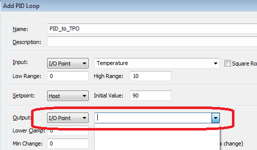
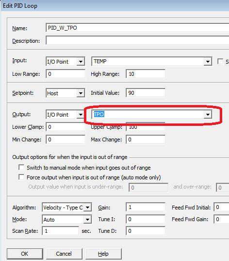
You CAN select it in PAC Manager, though, as shown here. (I’ve put in a request to engineering to add this missing piece in PAC Control.)


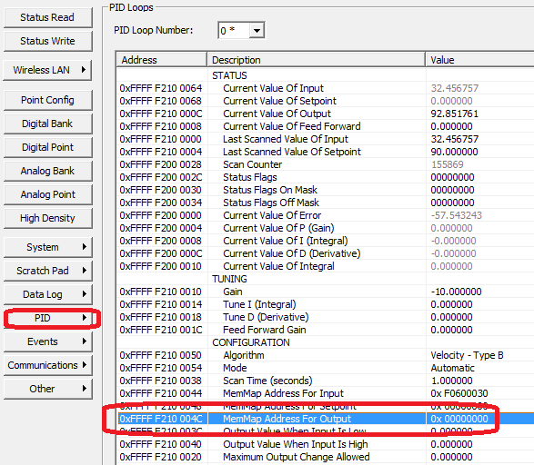
In the meantime, you can either use PAC Manager to configure the PID (don’t forget to save your settings to flash!) or you can add a little set-up logic in your Powerup chart to connect the dots between your PID and TPO. Essentially what you’re doing is filling in this Mem Map address for the PID’s Output:


The OptoScript would look something like this: (you’d need to change the 0, 5, and 2 – for the PID loop number (0), module position number & channel number (5 & 2) – to match your setup:

// Calculate the address in the PID configuration that’s the MemMap address for output (as seen in PAC Manager & form 1465)

// PID 00, change 0 to 1-95 for other PID loops
nPIDOutputAddress = (0 * 0x80) + 0xF210004C;

// This example has the TPO in module position 5, channel 2.
//In this code example, point numbers on the modules start
[SIZE=2]//at 0, so the 3rd point on the module would be point 2
// T[/SIZE]he mem map addresses are based
// on 32-point modules, hence the 32 in this formula).
nTPOPercentAddress = ((5 * 32) + 2) * 0x30 + 0xF08C4000;

// Write the address for the TPO’s percent into PID 0’s output location
nBrainWriteStatus = WriteNumToIoUnitMemMap( self, nPIDOutputAddress, nTPOPercentAddress );

WriteIoUnitConfigToEeprom(self);

Now your PID + TPO logic is all contained on the brain!

Hope that helps.
-Mary

2 Likes

Wow thats pretty cool Mary. Saves mapping events by using PAC manager. +1000!!

Interesting workaround to map the TPO output.

We’ve used several configurations.
Factory Floor, run a PID subroutine that was downloaded/adapted from old OPTOBBS, output to an AOD-29 module
With newer PAC systems, use the PID function, write to the host, then move the output to digital out as a TPO.
Also had a system that used digital outputs and a pair of timers to generate PWM output (prior to digital TPO options in PAC Control)

Started two timers (pulse period and duty cycle)
Pulse period (1 sec) and duty cycle (PID output divided by 100)
Set duty cycle timer and start both timers at same time.
Set heater output to be OUTPUT=NOT(hasdowntimerexpired(dutycycle))
Check if pulse period timer is expired, if not, loop back to set heater output
If yes, go back and reset/restart pulse period timer, get PID output, calc pulse on time, start dutycycle timer, set heater output

Now much easier using the TPO function on the Digital output.

Just need a good way of tuning that I can pass on to operators. We manage pretty well, but could be more efficient at dialing in the parameters.

Also if anybody has a good demonstration showing the differences in the different algorithms I would love to see that, help with selecting the right algorithm for different applications (1/4" tubing wrapped w/ heat tape, high temp furnace, heated bath, boiler, air line heater, pressure control, level control, etc.)

We used many AOD-29 for our projects and also I used TPO output logic for my another project. Where one of my chart getting value from PID output and update that to TPO output. In my project I have 3 different PID control one output so in my logic I have to update maximum output from those 3 different PID. Might be I can use some of this information and implement logic so it will improve performance

One application that I’ve been looking at is using a PID to set a TPO that drives a proportional solenoid. The load from the solenoid is reasonable (24V @ <100 mA), but needs a fast enough pulse to prevent ripple. The solenoid would ideally be powered by PWM of 1500 Hz. The AOD-29’s .25 sec min period eliminates it from consideration, so the 850 µs combined turn-on/turn-off time of a digital output module looks better. PWM of 200 Hz might be worth trying, slow enough to get some resolution in the PWM but hopefully still fast enough to create a reasonably smooth response in the process. I might also just cave and pick up an external PWM generator and drive it with a standard 4-20 signal.

We had an email come into Opto about this topic today, and it listed this thread as a ‘great help’…

Having just re-read all the discussion here, I just want to throw this out there for consideration…

Sometimes its worth taking a step back and seeing if we are over thinking or over complicating this whole PID/TPO configuration/tuning.
What do I mean?

The customer has an application where they manually raise the temperature to a certain point, and then switch to automatic to have the strategy maintain the desired temperature (their set-point).
Since they are manually controlling the start up, I wonder if overshoot is an issue for them?
Lets, for the sake of this discussion, propose that its not an issue, they get the process up to the set-point and then switch to auto.

What I’m proposing is that you don’t have a PID taking care of things from here.
Once the strategy see’s the switch go into auto, it starts a very simple chart.

If the process is more than X above the set-point, turn off the digital output.
If the process is more than Y below the set-point, turn on the digital output.

X and Y will take a few cycles to tune and get a feel for how much swing your process can tolerate, but I wonder how many processes could have such simple control and keep within specification?

Whats the down side? Slope. The main thing a PID gives you is that it looks at the rate of climb or the rate of decline and can switch the TPO (digital output) ‘before’ it needs it (only if you have it tuned correctly and for that set of conditions).

One memorable loop at the hospital needed three sets of PID values and I used the strategy to switch between the three depending on the state of the process.
It was a dog to tune and soaked up hours and hours of my life.
In the end, I threw out all the PID/TPO stuff and just switched the output from the strategy. Better. Much. Better.

As I said, its not for every process, but sometimes its worth thinking about the simplest solutions?

This was very helpful. Just as a note, I tried to configure these with PAC manager and it displays some odd behavior: it lists the correct output point on the PID configuration screen, but, when you close that screen and look at the list of PIDs, the output is listed incorrectly (as in input point, in my case). If you inspect the unit after loading the configuration, the address listed for output is off by 4 (hex) from the numbers Mary provided (which are the correct numbers)…this maps the output to the TPO period rather than the percentage. Got around it by just manually calculating the points and putting them in the memory map values section of the configuration file, but it’s a little convoluted.

Wow, thanks for the info, tricia, and welcome to the OptoForums! I’ll let our PAC Manager developers know so they can iron this out for us ASAP!

FYI all you PID + TPO users, this PAC manager issue that Tricia describes above has been corrected and will be in a future release of PAC Project. If you need this Beta (B9.3c) sooner, contact support @ opto22.com or send me a note.

Any update to this issue? Has it rolled into the released version or is it still in beta? I’m managing several liquid heaters using PWM, one of which definitely needs a PID loop to set the TPO. Is it still best to just use PAC-Manager? Thanks!

Hello RedClay,

Welcome to the OptoForums!

The soon-to-be-released PAC Manager update should be coming soon (are you subscribed to OptoNews?) but if you need it sooner, contact our PSG (Product Support Group) for the beta (B9.3c).

The fix to PAC Control is NOT scheduled for that imminent upcoming release, but I’ve put in a request to bump that up on the priority test.

-OptoMary

[QUOTE=mstjohn;1456]
// This example has the TPO in module position 5, channel 2.
//[/FONT]In this code example, point numbers on the modules start
[SIZE=2]//at 0, so the 3rd point on the module would be point 2
// T[/SIZE]he mem map addresses are based
// on 32-point modules, hence the 32 in this formula).
nTPOPercentAddress = (([B]5 [/B]* 32) + [B]2[/B]) * 0x30 + 0xF08C4000;

Where did you get the (I am assuming) base address of 0xF08C4000? I can’t find this anywhere. I interface the Opto Brains using purely OptoMMP and I cannot find that address anywhere in the guide. I also can’t seem to find much information on TPO for digital outputs (found the analog SNAP-AOD-29 and high speed equivalent). If I could get PID to work on standard digital outputs it would be great!

Regards,
Scott

Hello ScottMorris,

Welcome to the OptoForums!

Ah, but you [I]did [/I]find that base address, right here! :cool: That’s one of the fun things about the OptoForums – sometimes we share stuff that’s NOT documented anywhere else. I’m hoping that everything you need to configure your TPO for PID is listed above. (Like in post #4 above, where I show some PAC Manager screens?)

I’m guessing you might want to know: WHY isn’t it documented? In the case of this TPO/pulse feature, most people use PAC Manager or PAC Control to configure those features. The mem map is actually pretty hairy for those pulsing features, which is why we recommend using PAC Man/Control if at all possible.

Using PAC Manager to configure your PID/TPO, you can store to flash and even “clone” one MMP device onto another if you like (no need to write code, necessarily). By clone I actually mean use the PAC Manager feature under: Tools > Import/Copy I/O Unit Image…

But perhaps you could tell us more about your application? I might have some other tricks up my sleeve that could save you some icky mem map programming!

-OptoMary

Has the issue with brain images and 8-channel analog input modules been fixed? When you pull an image from a configured brain, the scaling on points 4 and up on any AIV-8 modules (and maybe others?) gets blown up so when you send that image back to another brain, the scaled unit is incorrect for those points. I reported the issue a while ago and received a 9.3f firmware beta, but the fix didn’t seem to make it into 9.4a.

Mary,

Thanks for the reply! Yes, I did find the base address here for the percent but not for the period or how to setup the point for TPO.

I work in R&D and build many prototype one-of-a-kind machines. With that in mind the software guys have tried to keep all the software in one location. It simplifies development of a new machine if the only place you have to write code is on the control computer. You don’t have to worry about what is on any particular brain or starting up some other programming language/software. It also has the added advantage if a brain dies for some reason replacement is dirt simple. So the way we use Opto equipment is to build the racks with modules and a Ethernet enabled brain (usually an EB1 or EB2). We write all our control code on the Linux control computer. The control code connects to the brains, configures them, sends and receives point information as needed. The only time we use PAC Manager is to configure the IP address. Although you may say that mem map programming is icky but that is the only thing we do. We have been using Opto equipment since the late 90’s and plan on continuing but we are always interested in new features that we can take advantage of.
It sounds like in order to get access to these features I would need to start up PAC Manager to find the proper addresses for all these features and create my own documentation.

Regards,
Scott

Hi Scott,

As the person who wrote the (not-really-so-icky) mem map pulse programming code in the control engine, I’d strongly advise against reverse-engineering the rest, I’ll PM you to get details of what you need, exactly.

However, fair warning, (not sure I mentioned this disclaimer earlier) the other part of why we have not yet officially documented this part of the mem map is that it’s still subject to change. There’s a possibility that in a future version (perhaps 9.5? 10.0?) of firmware/PAC Manager/PAC Control, we might change some details of how these pulsing feature works.

But perhaps if more people need/want this, we’ll up the priority on getting something official and documented on it!

Thanks,
Mary

I would like to put in my vote to allow the TPO configuration in PAC Control. I plan on using this method on a project I am working on that involves controlling some thermo-electric wax actuators for some fan coils.

I already have Mary’s method written up (thanks!), but configuring these in PAC control would help the next guy that looks at this project.

Ben’s method would probably work on these devices too, with one exception that I see. Since my strategy is running on a PAC-S, if we lose network connectivity, then we lose control of our valves. They will end up full-on or full-off (binary is wonderful like that). By strategically placing the controlled points on the same rack as the control points (discharge air temp in this case) and using the brain to do the loop work, everything will (mostly) continue to function during a network outage, local power issue, reprogramming, debugging, etc.