One of our OptoPals asked this question re: under/overrange. The main thing that popped in my brain to watch out for is qnans, as I mentioned in the “SANITY CHECKING” of this post on totalizing.
Anyway, here’s his whole question and his approach to solving it. Any/all ideas and comments appreciated, as always!
To monitor if an analog input is within an acceptable range we do one of the following:
Bring in raw 4-20ma signal into the controller, measure if we are within acceptable range (ie. Bad if below 2ma and Bad if above 22ma) then scale the input into Engineering Units within the control system. Not a big fan of this approach since it eliminates scaling at the IO level.
OR
Bring in the scaled Analog Input and setup the allowable range that indicates the input is good / bad. (ie. 4-20ma is 0-100% so we would indicate Bad if our input is below –12.5% (2ma) and Bad if our input is greater than 112.5% (22ma))
Of course if the input is bad or module pulled, we see the large negative number which also tells us that the input is bad.
In the above cases, we need our logic to react to bad inputs to prevent process issues and/or provide an alarm that we have a bad input.
The problem with this approach is that we need to adjust our range for each input and in the case of a 4-20ma input the module doesn’t indicate a bad signal at 0ma (bad for a 4-20ma input) since the input module is setup for +/-20ma. This becomes a bigger issue when input ranges change (after installation) which requires additional logic modifications that always seems forgotten when our customers do it themselves. With thermocouples, RTD, etc. we will still need to setup a range monitor since a “good” input signal may actually be bad but once setup these ranges should never change.
Is there another way to “easily” monitor that the input is within acceptable range? Primarily for 4-20ma or 1-5v inputs.
Is there a way to setup the allowable range of individual inputs on the initial start of the system so we see the bad quality (large negative number) when we go outside the preconfigured range?
I thought about memory mapping and getting the actual counts but this seems like more work than doing what I’m currently doing.
…this may be a stupid question (either I’m missing something or I’m already doing it the correct way). I’ve been doing input monitoring as I noted above for a long time (and it works) but that doesn’t mean is the best way to do it.
I prefer scaling in the IO when possible (if the point isn’t reverse scaled). I then check the range using the engineering units, since as you mention, the module range (4 to 20mA, -20 to 20mA, -10 to 10v, etc.) may be valid, but can be well outside what you want in your process. I don’t think there is a one size fits all on this, and I think your approach is valid. Customers changing the IO input ranges is not something I have ran into…
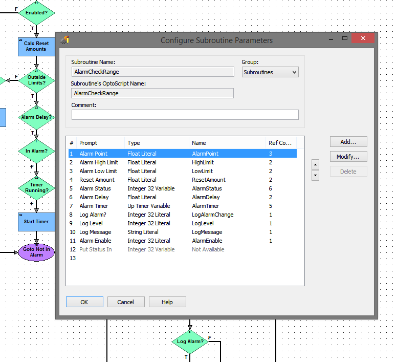
Checking your inputs, and alarming on out of range values is such a common procedure that I have a subroutine for this. I set it up to allow for time delays and reset hysteresis, and it made the alarming in my control charts concise and easy to configure. I could then alarm in PAC display by checking the discrete alarm status variable I setup for each point, and I also could optionally log a message to the controllers message queue.
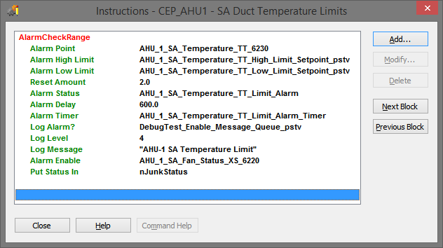
Here is a screenshot of the parameters to get an idea/inspiration:
Notice that the limits are variables (persistent) that the operators can reconfigure if needed. In others I have hard coded values. I also have a similar subroutine for digital/discrete values.
Keep in mind that @philip wrote the subroutine for his method of building strategies thus it will be very custom to his requirements.
We don’t have (at this time) a central place where user charts or subroutines are posted. Mostly because of my first comment, the logic is usually very customized to the needs of the user and their process. It’s usually quicker to build what you need than to modify someones else’s work.
It is always useful to see how someone else is doing something or approaching a problem to refine ones own thought processes, particularly when first starting out. For example Mary’s Totalizer Sub she posted is an excellent generic Sub that has a lot of good features built in that can be used in a number of different cases. Some other basic functions that are used frequently and could be beneficial to the community:
Basic single speed Motor operation
Runtime Totalizing and Start Counts
Lead/Lag/Standby motor group
Analog Alarm function (Similar to Philip’s Sub)
Digital Alarm function
Allen Bradley actually provides these types of things as addon instructions with associated HMI objects (they even provide tech support for them). This makes development of control code and an HMI a breeze particularly for standard process applications. Having to reinvent all this code (or invent it once for yourself) for each project is a major drawback not to mention having to figure out someone else’s solution while troubleshooting. Maybe that is one of the next steps in Opto22’s journey to providing the go to PAC…