A question about ODC5R
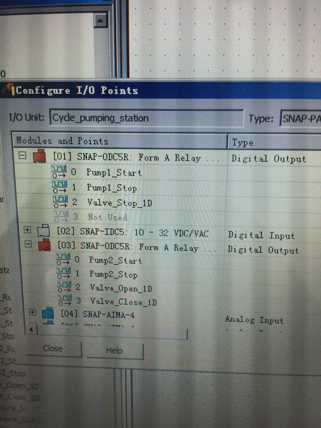
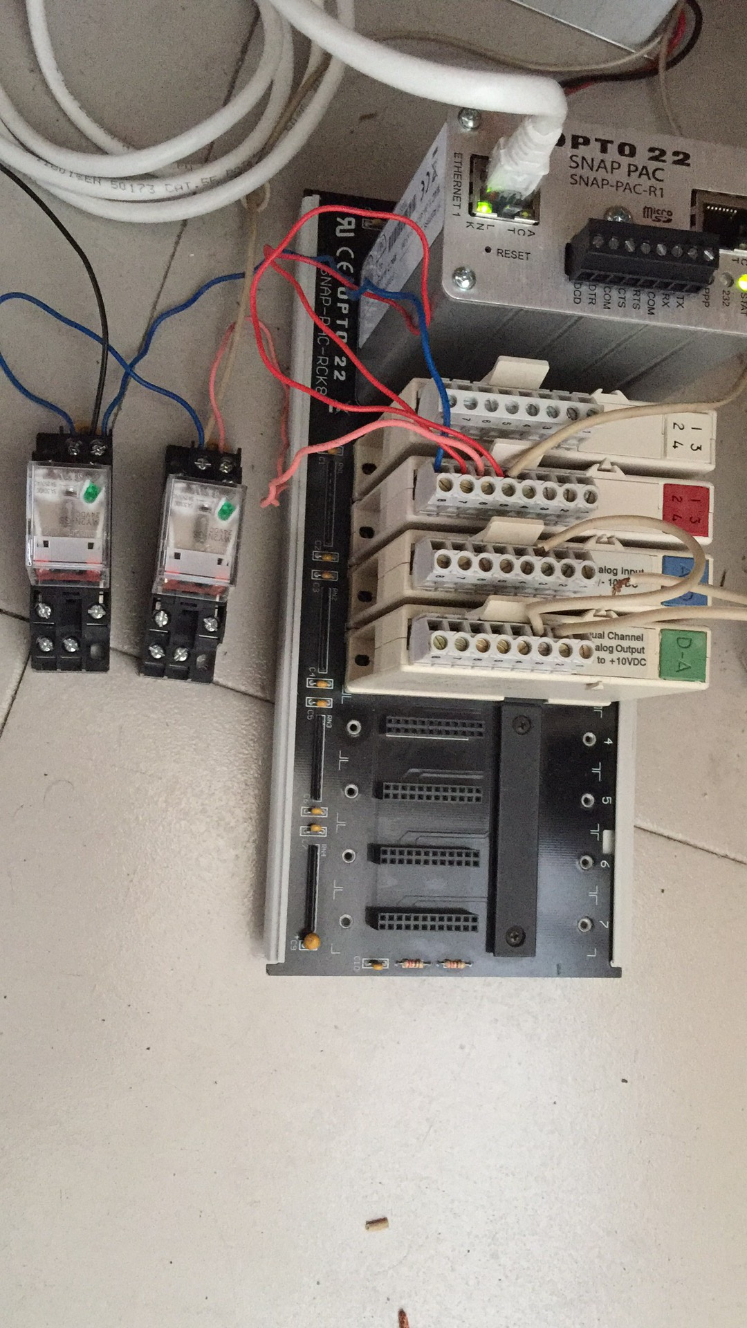
The customer used ODC5R to control the DC24V relay. It has failed for two ODC5R in two consecutive months. Each ODC5R module has been in normal use for about a month.
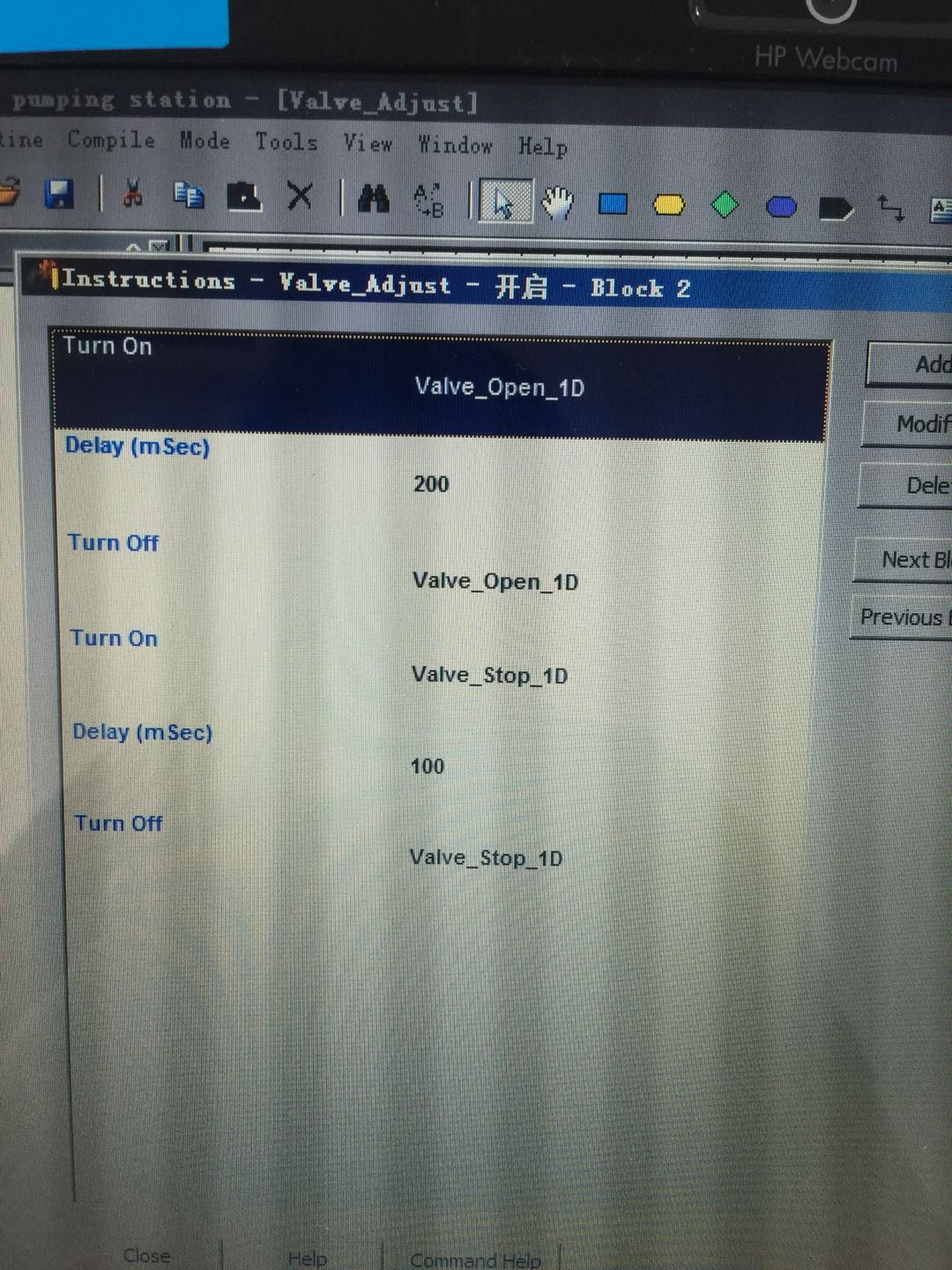
Malfunction: the channel indicator light on ODC5R is not bright, but the relay it controls is in a closed state. When I pull out the terminal block on ODC5R, the relay loses power.
The control of the relay is very simple, but the operation is very frequent.
1, is there any problem in using this way?
2, if there is no problem, what is the cause of the failure?
I’ve changed to ODC5I, and I’ll watch it for a while.
The http://documents.opto22.com/1949_SNAP_Reed_Relay_Modules_Data_Sheet.pdf says the relay contacts can handle 416 mA at 24 volts. It also says to use a commutating diode when switching inductive loads. Since the load is a relay, does it have the required transient protection diode, and does it pull more than 416 mA when actuated?
The module has a very small reed relay, in your application the contacts are welding together, so the output is always on. The module LED switches correctly, but the contacts are always closed due to its failure.
As @dougm said, you must use a diode at the least, but in short, you have the wrong module for the application.
This is indeed our fault.
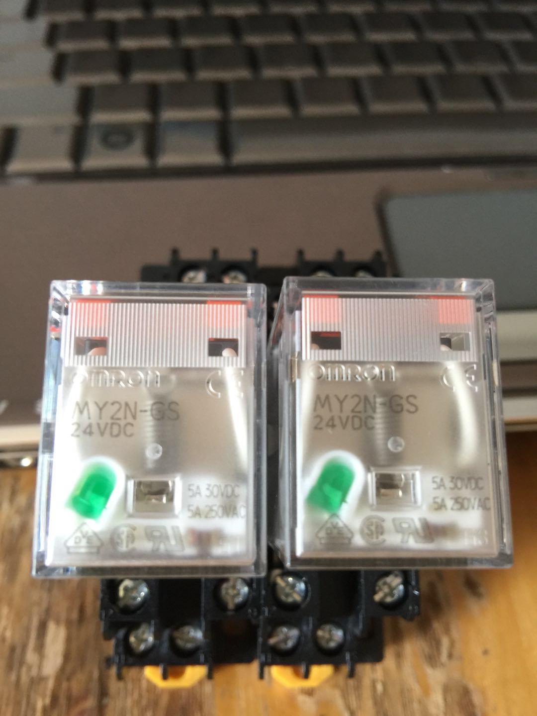
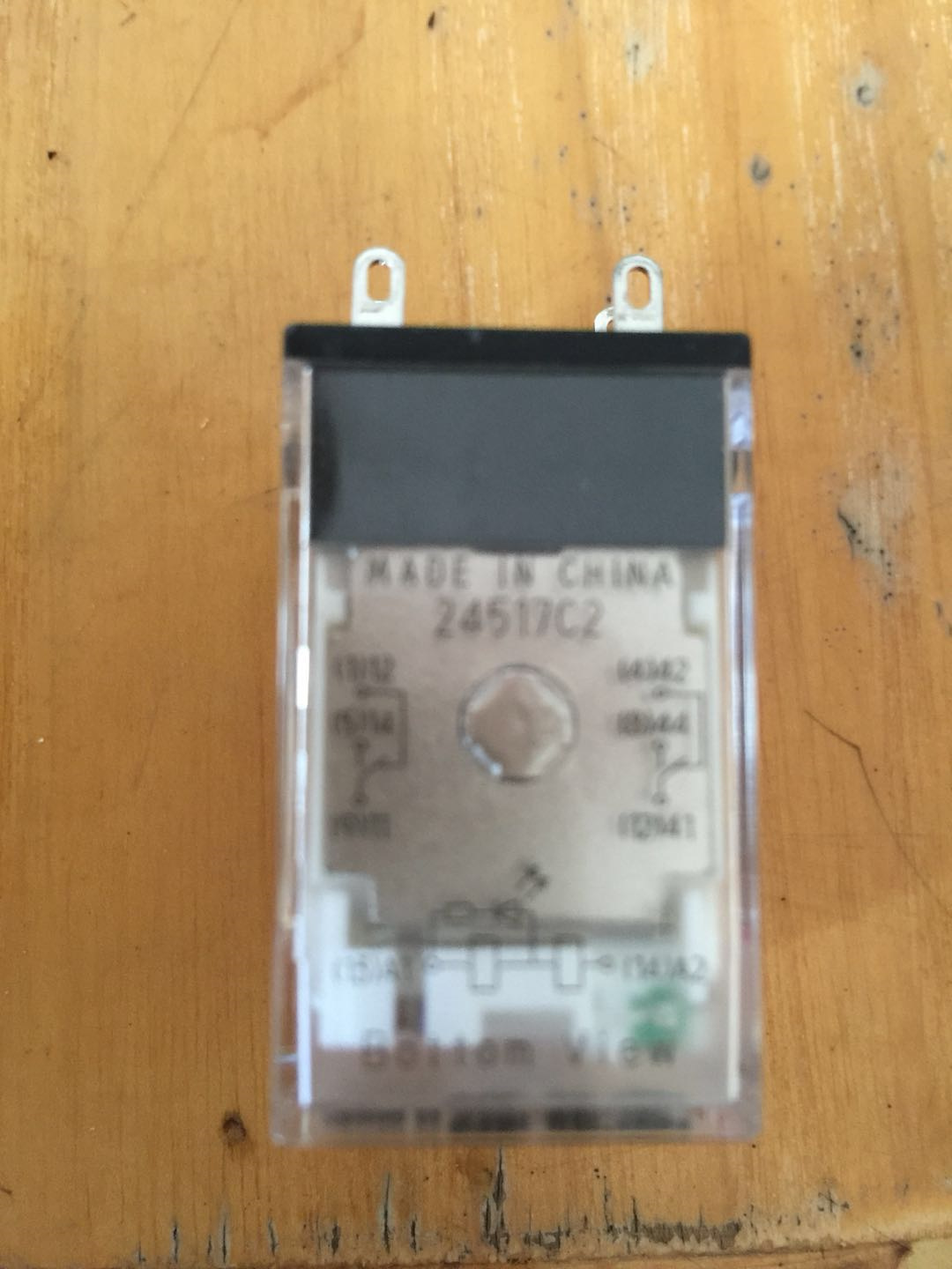
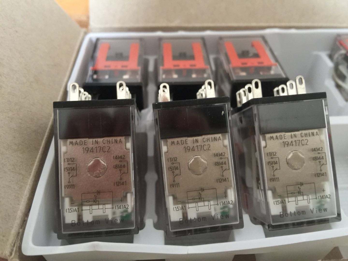
Customers use this kind of relay. The working current is only 40mA and the action current is 60mA. Because the current is very small, he does not use commutating diodes.
Excuse me
1, now the customer has used IDC5-i instead of ODC5R. Is it necessary to use commutating diodes?
2. Is the commutating diode model 1N4005?
Without a flyback diode, you could be hitting hundreds of volts across the reed relay when it opens from the inductive flow of the relay coil. Adding a 1N4005 should work fine for a flyback diode, I’ve used them on 24VDC coils without issue. Install them at the relay coil terminals is best.
Another option is to get a relay that has a diode accessory. It will be less likely for it to fall out in the future, and no way for someone to put the diode in the wrong way. More expensive, but cheaper than a new module.
By the way, Omron MY2N-D2-GS would have the diode built-in. Looks like they are buying the kind without the diode. Probably very little cost difference.
Very strange. I tested the customer’s problematic ODC5R in the office. Let it move at a very high frequency, 10 times faster than the scene, and run normally for 24 hours.
Why?
Electrical noise and wire length can be quite different in the field causing the voltage spikes to be considerable higher. Just like others indicated you would want the diodes. I have experienced these issues in my past also with other manufacturers of REED’s and the diode helped.
Are you sure a ODC5R is the best module to be using for this? Since you know you are controlling a 24VDC coil, I think you could use a ODC5A or ODC5SNK/SRC. You still should have a diode on your coil, but these modules would probably be more forgiving (they have a diode across their outputs already). You will also get a longer warranty on those modules.
Thank you for your help.
The use of ODC5R is just because there are such modules in the customer’s spare parts.
It has been corrected according to your suggestion.
Replace ODC5R with ODC5-i.
2, replace MY2N-GS with MY2N-D2-GS with flyback diode.
Thanks again!
I would include a flyback diode. The datasheet doesn’t mention anything about it on the high density modules, but does show a maximum off state voltage of 60VDC. Since the coil (inductor) in the relay can generate hundreds of volts when it is switched off, you will want to handle this.
How much are a handful of diodes?
How much is a ODC-32 and the associated down time?
I realize that this is an old thread, but I thought I would mention something that we discovered many years ago when implementing this sort of setup.
When you use a commutating diode across the coil of an interposing DC relay, it does a good job of protecting the contacts (or transistor) in the output device driving that relay.
But because that commutating diode provides a low-loss current path for the coil being driven, the magnetic field in that coil (solenoid) collapses far more slowly than it normally would when your system tries to switch it off.
The result is that the contacts of the interposing relay open much more slowly than they might otherwise. And that leads to more arcing and damage to THAT relay’s contacts if IT is being used to drive an inductive load. As its contacts slowly open, and they attempt to interrupt the current through ITS inductive load, their slow separation encourages the development of an arc, establishes the conductive plasma, and burns those contacts far worse than if the contacts separated rapidly so that the arc gets quenched faster with the contacts opening far enough to overcome the voltage being generated by the load.
Of course, that load or the interposing relay’s contacts should have their own snubber or protection.
But the thing is: If you use an MOV instead of a diode across the interposing relay’s coil, that coil energy is dissipated far more rapidly, and the coil current interrupted faster, allowing the magnetic field to collapse far more quickly, and letting that relay’s contacts pop open faster so that IT doesn’t suffer as much contact damage if it is called upon to control an inductive load.
This can also be important when driving DC solenoid actuators. If you don’t want them to release in a sluggish way, use an MOV around their coil, and not a diode.
MOVs are also good for use around AC coils, motors, solenoids, etc. Sometimes this is better than using a snubber.
I like Littelfuse’s documentation for their MOVs. They give all of the pertinent specs. The hard part is trying to guess how much energy the inductive load will apply to the MOV. But you can’t go wrong overestimating the energy, and getting too large of an MOV.
The main thing is to select one that will limit the peak voltage to a value well below the rating of the transistor or relay contacts that you’re protecting, but well above the expected supply voltage for the coil or inductive load.
This is usually not hard because the transistor or relay’s contacts should be rated for a much higher voltage than the supply voltage of the thing it’s driving.